LVR burn-in operations
Overview
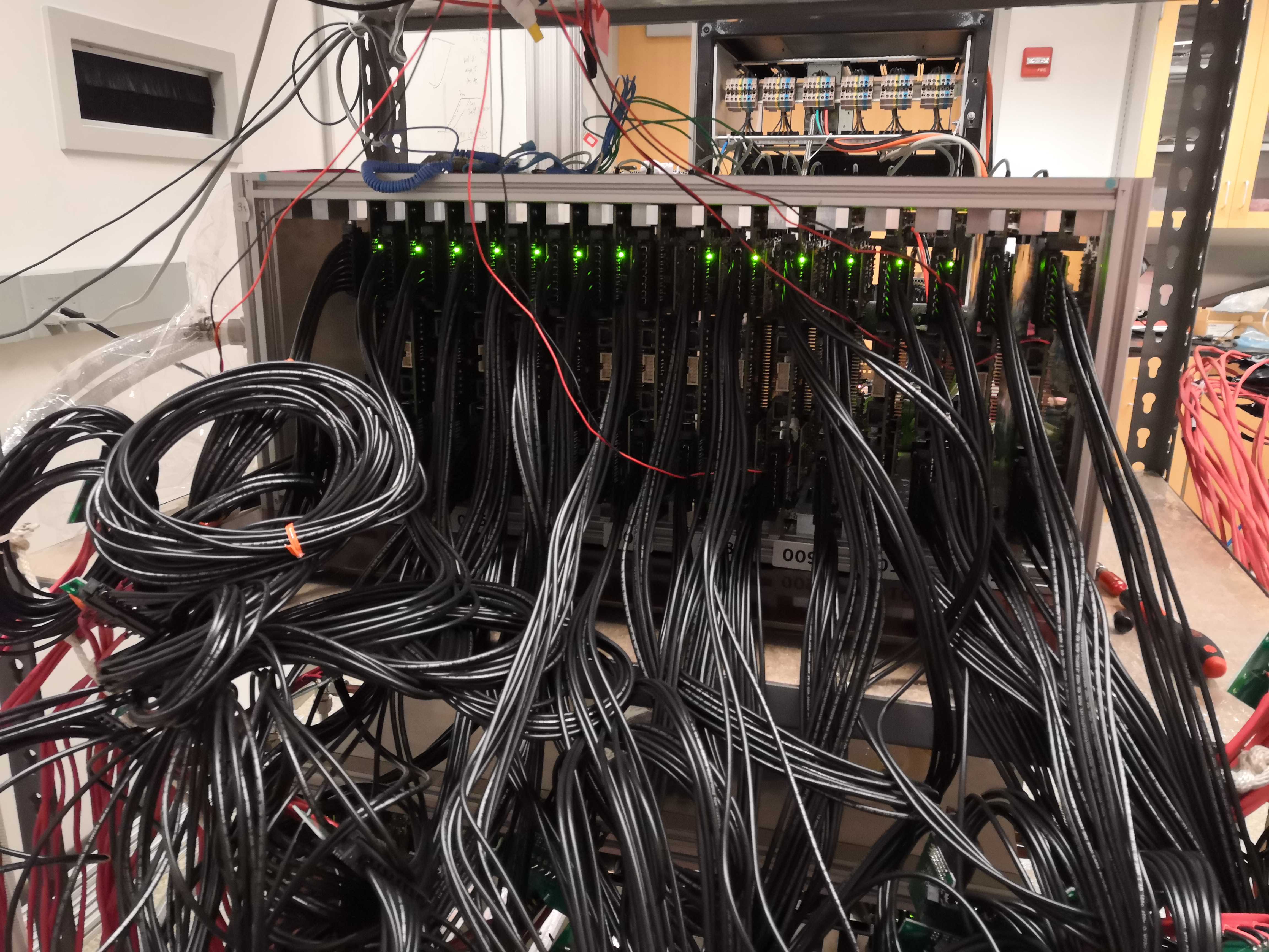
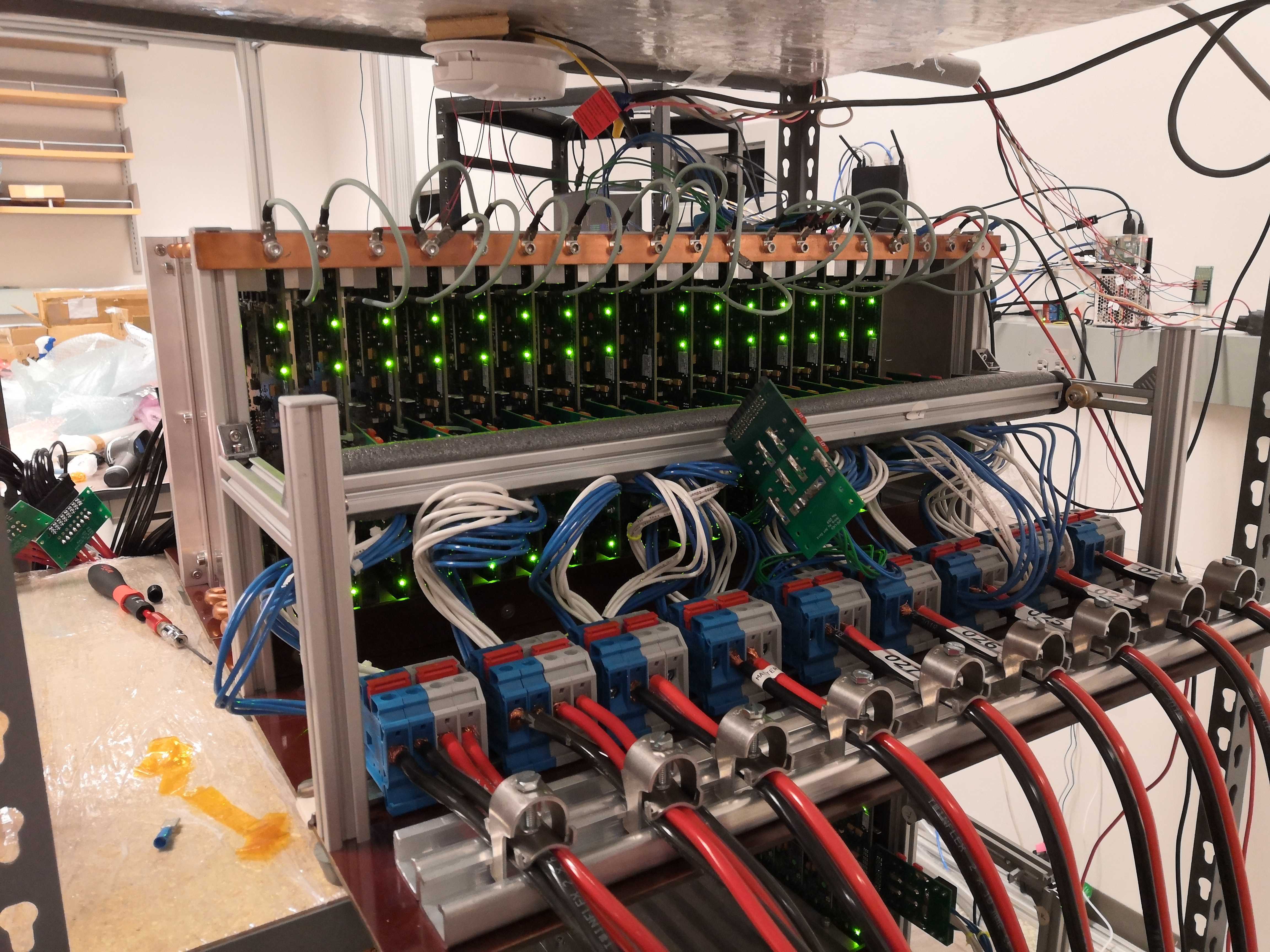
Currently, LVR burn-in maximum capacity is 16 boards:
- 2 x
2V5(using Switching Load Boards labeled 2V5) - 14 x
1V2/1V5(using the rest of Switching Load Boards)
Each batch should be burned-in for 48 hrs, with switching loads and thermal cycles. The current profile is:
-
switching between high current (2A) for 60s and low current (0.5A) for 10s
Info
So that voltage regulator chips are frequently exercised by changing states, while in typical operation (high current) most of the time
-
bang-bang controlling board temperature between ~30C and ~50C
Info
For reference, constant-cooling equilibrium is ~30C and overtemperature lockout is 70C.
Start burning in a new batch
- Inspect the "ready for burn-in" box and decide on the LVR types
- Update the database according to the selected LVRs' IDs
- Check to make sure that wedgelocks' allen heads are facing the output side, not the input side; and verify the switches as indicated in the table below. Order refers to toggles 1234 on the switch, with
1meaningON. (CCM) or (FPGA) refer to the side of the LVR the switch is on. There are four SW6 switches.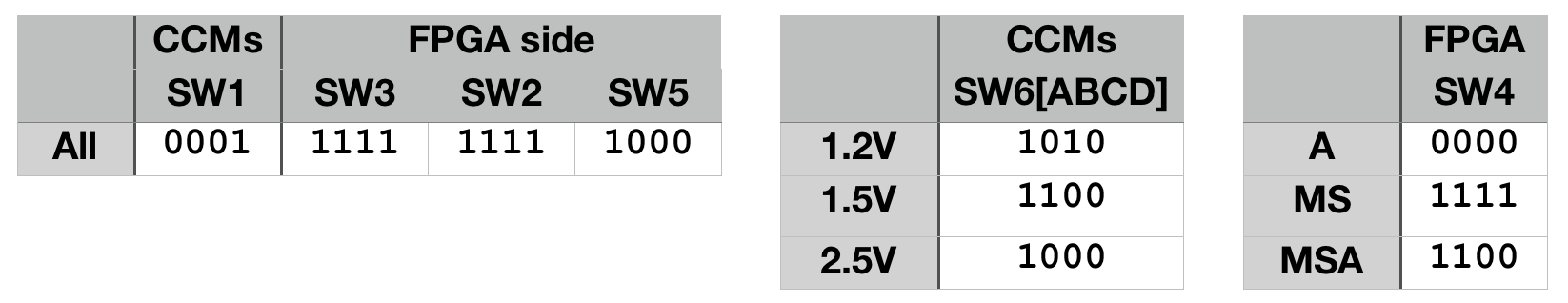
- Mount LVR in the SBC, and double-check that wedge locks are tightened
-
Check the status of Maraton
Warning
If it's already running for DCB burn-in, be careful not to touch exposed live wires in the lower SBC
-
Attach thermal sensors on 4 boards:
- put sensor's flat side against an open area of the board (without SMD componments)
- press the sticky putty to secure sensors in place
- you'll have more room to work with before installing adjacent boards
-
Connect the output cables to LVR (the connectors should click), and verify that 2V5 switching load boards are connecting to two LVRs in Maraton channel 11.
Info
The output breakout boards are labeled for 2V5
Warning
As you connect the output cables, take care not to pull thermal sensors away from the boards
-
Now install the input breakout boards and grounding cables:
- move the horizontal bar back to make space for installation
- because there are 2 input breakout boards per Maraton channel, connect the pairs in order (e.g. from right to left) to not mix between channels
- input breakout boards are hard to secure even with the bar, so sometimes zip ties are needed (2V5 slots in particular)
- check that the cables to the input BBs are tightly connected to the block terminals (they gradually loosen and should be tightened again)
- after all boards are connected (some horizontal tilt unavoidable), push in the boards and fix the bar to keep boards in place (with quite some force, try starting from one end and push in one input BB at a time)
- double-check the connectors, especially for vertical tilt (resulting in partial connection)
- verify grounding cable connection
-
Double-check that the chiller is on
-
Turn on the Maraton
-
Start running the python scripts as described in here
- Note that you need to use
Ctrl+bthen arrow to switchtmuxpanel - You can use
Ctrl+rto reverse search past command lines
- Note that you need to use
-
Turning on one Maraton channel (channel numbers are labeled on SBC) as described in here
- after issuing command, verify all LEDs are on: 1 in the front and 4 in the back. If not, turn off the channel and check connections (e.g. only 4 LVR channels on due to partial input connection). Often the last few channels (11,10,9) need adjusting input BB connections (e.g. pushing in more).
- use multimeter to spot check voltages across the output connector solder joints (or output breakout boards) -- should be the set voltage plus some drop (e.g. 1V5+0.2V)
-
Repeat for other channels
- At this point, all LVRs are running with low currents, before load-switching (seeing 5 Ohm fixed load)
-
Make sure that the Switching Load Boards' secondary voltage supply is on (5V, 0A), and the cooling fans are on
-
In another panel, start running the
SwLoadTest.py(src/demo/SwLoadTest.py)Note
Verify the changing current (2A/0A) on the voltage supply
-
Now Switching Load Boards are in working state, LVRs are changing between high/low-current states and heating up quickly
-
Go to monitoring website and verify the temperature measurements (should be going up from ~30C)
-
Monitor and wait for the upper temperature target (40C), and verify the USB relay switched on (click and red LED)
Info
Now valve is open for cooling water
-
Use FLIR camera to check for abnormally hot (>60C) spots, both on the LVRs and the SLBs
- Give yourself a pat on the back -- burn-in has started
Stop the burn-in
-
Before turning off the Maraton channels, check that:
- In the web monitoring history, each Maraton channel's current did not deviate from its high and low values (e.g. reducing to half if 1 LVR stopped working)
- all 4 LEDs on the back are on (indicating all 8 LVR channels have been on).
- no hot spot >60C on FLIR
- Spot check voltages on output breakout boards, e.g. 1V5 + ~0.2V drop. Very carefully probe between two adjecent groups of pins on output connector (slowly move one probe at a time to avoid shorting). Will add picture here later.
-
Turn off Maraton channels one by one.
Note
Verify that the front LEDs are off
-
Stop the control and monitoring scripts (
CtrlServer.py,CtrlClient.py,SwLoadTest.py) byCtrl+CNote
You need to use
Ctrl+bthen arrow to switch tmux panelSome transmission failure messages may have covered the panel running
CtrlClient.pyFor future convenience: after scripts are stopped,
Ctrl+Lto clear, then up arrow to bring up the last commandNote
USB relay should be automatically set to open (no red LED on) when scripts are stopped, if the last measured temperature is higher than the lower target (31C). If relay is closed, the DC power supply will keep pushing the solenoid valve on (not ideal). To open it by command line, refer to the burn-in software doc.
-
Disconnect the output cables and hang them by their clip on the red wire.
-
Disconnect the input breakout boards (after moving the SBC bar)
Note
Check for loose connections to the terminal blocks (can gently pull to see if a wire is loose)
-
Disconnect the grounding wires
-
Loosen the wedge locks and take out LVRs. Detach the thermal sensors as space around LVR opens up.
Warning
Take care not to pull wires off the sensors' leads
Note
Wedge locks should be loose after 3 complete turns. If you still have trouble moving the LVR, make sure it's not blocked by the crate's bottom horizontal rail.
-
Put the LVRs into ESD bags, and update the database
Monitoring from off-campus
To visit the monitoring website from off-campus, you can set up VPN this way:
-
Install the VPN client software from UMD terpware. (You want to select your OS and find it under Network.)
-
Login with your UMD account to connect to vpn.umd.edu (and select Group UMD)