CERN QA
DCB CERN QA
Note
All these procedures are automated by a single WinCC OA panel, please refer to this section below on how to use it.
The DCB CERN QA will test the following aspects of 2 DCBs for a single run:
- Run regular GBTx PRBS test for 2 min.
- If there's any PRBS error in the previous step, re-run PRBS with 6 mA1 bias current for 2 min.
- Run SALT PRBS on available elinks2 for 2 min.
- Read master GBTx status via optical link to make sure master is configurable this way.
- Read all ADC lines that will be used in the final system.
Remove DCBs from PEPI crate
Before you proceed
To appease the accelerator god(s), wear anti-static straps at all times and install caps on fibers immediately after removal.

Open the MARATON control panel
- Make sure to have a LHCb online account
ssh -Y <lb_username>@lbgwssh -Y <lb_username>@utsurface01WCCOAui -proj UTSURFACEHVLV -m gedi &- Open JCOP Framework -> Device editor and navigator -> FSM tab
- Navigate through the tree: UTSURFACEHVLV -> UTSURFAC_LV_MTV -> UTLABMTN3, then right-click and select "view"
Before turning on the LV
Make sure to turn on the chiller on the top floor before switching the LV: 1. Check that the kill switch in the front in on. 2. Press and hold "enter" to turn on the chiller. 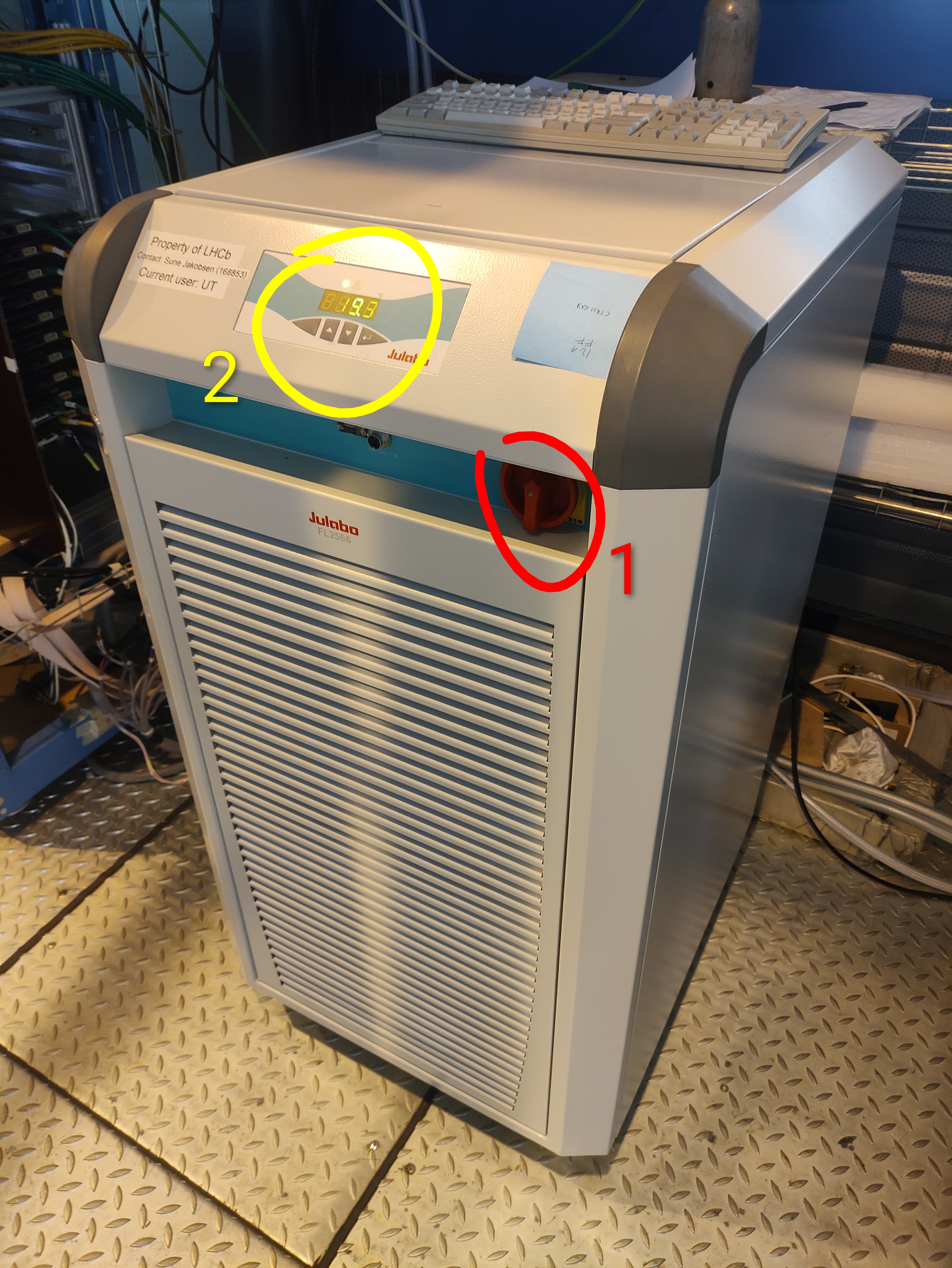 To turn it off, first hold "enter" and then flip the switch.
Note
We are only using the one DCB slot on the bottom Pathfinder, slot 4 (the 5th from the left).
- Turn off bottom power3 with the power panel on the MiniDAQ by clicking Bottom OFF (don't worry about the warning on the panel that this button is "only for testing").
- Turn off the 3V pull-up PSU:
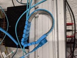
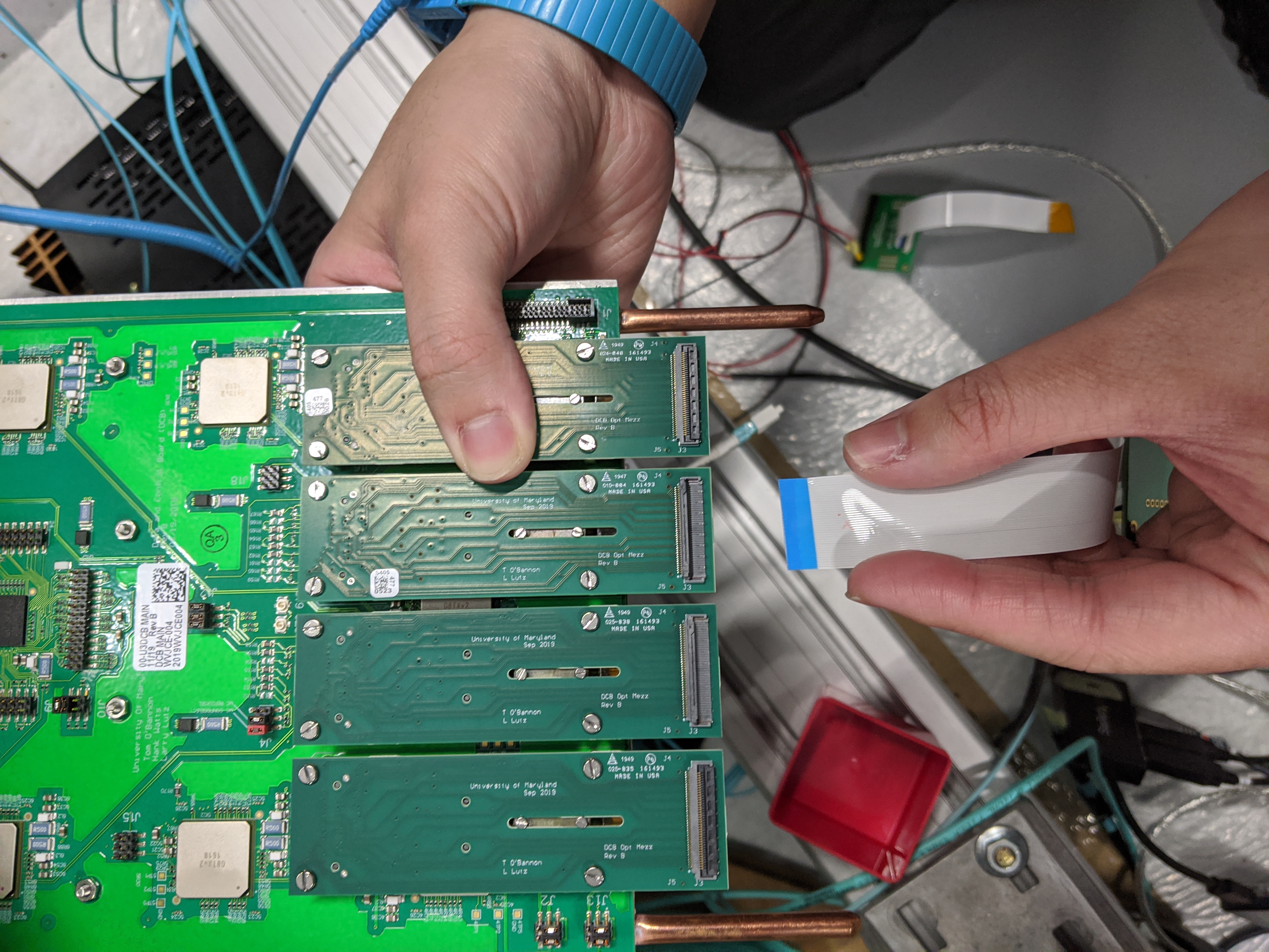
- Pull out DCBs one-by-one, then remove all fibers and FFC4.
Install DCBs to PEPI crate
-
Install FFC to the DCB.
Note
- The 2 FFCs are interchangeable.
- The FFC should be inserted to the second to right of the opt. mezz, when the copper pipes are pointing down (see the picture for FFC removal above).
- Try to do this step carefully, making an effort to ensure the FFC is straight and making good contact. This will potentially save time, since a bad FFC connection is often what causes a QA failure.
-
Install optical fibers to the DCB.
Note
The left DCB slot is
JD0, the rightJD4. The topmost fiber (in the FFC removal picture above) is1.Therefore,
B0.4means the 4th fiber from top in slotJD0. -
Install DCB to the correct slot (the one with
B0.xfibers must go toJD0,B4.xJD4). -
Double check the pull-up harnesses are still connected on the FFC breakout board. If not, reconnect them according to the picture below (red on third from top, black on fourth from top).
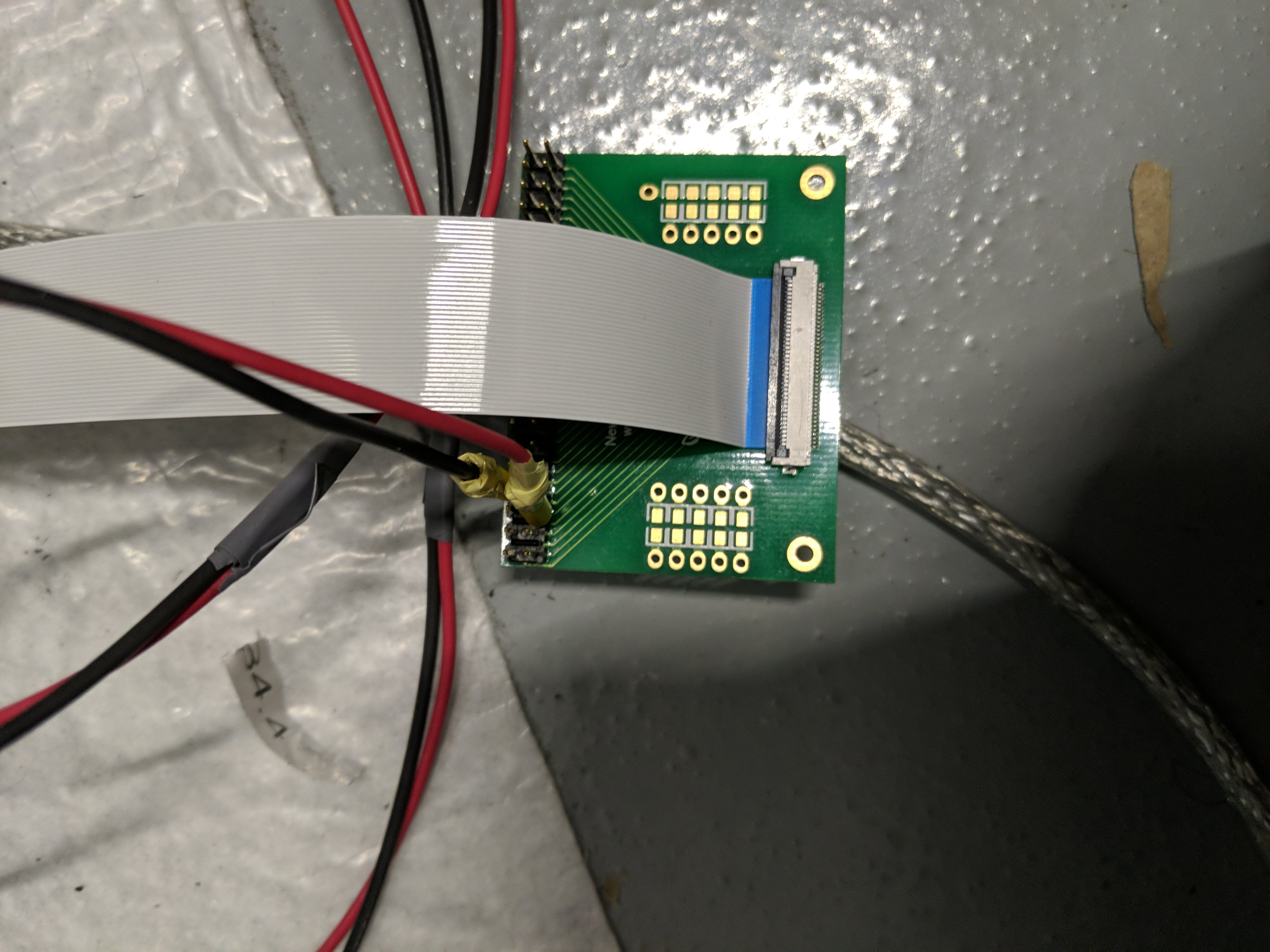
Also make sure the other ends are still connected to the 3V pull-up PSU.
-
Turn on the 3V pull-up PSU.
- Turn on bottom power with the power panel by clicking Bottom ON.
Use the DCB QA panel
Info
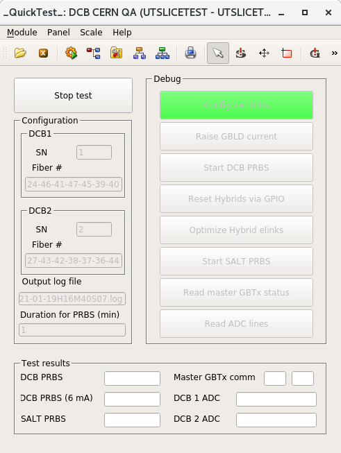
The panel looks like this:
The UTSURFACETEST project lives in utsurface02. To connect, ssh into lbgw then
ssh -Y <username>>@utsurface02
Info
The log viewer can be launched from command line with:
WCCOAtoolLogViewer -proj UTSURFACETEST &
The main user inteface, gedi can be opened with:
WCCOAui -proj UTSURFACETEST -m gedi &
Next, open JCOP Framework -> Device editor and navigator -> FSM tab, then naviate through the tree: * UTSURFACETEST -> UTSTAVETEST, right-click and select "view".
-
Once connected to
utsurface02, launch the DCB CERN QA panel:WCCOAui -proj UTSURFACETEST -p objects/fwDCB/UT_DCB_CERN_QA_v2.pnl &Establish a working baseline
Now it's a good time trying to read the status of master GBTx, to establish a working baseline.
This can be done by clicking the Read master GBTx status on the Debug buttons.
If you see one or two of the master status can't be read, like this:
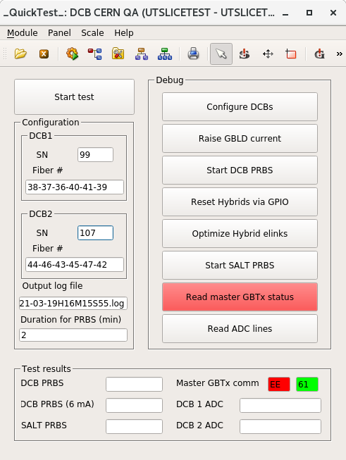
then turn off powers and try reseating the FFC! It is very likely that the FFC is not making good contact!
If after reseating and swapping FFCs, the master status still can't be read, put the board aside, mark it as bad, and install a new board.
-
Input the serial numbers for the 2 DCBs in the SN fields
-
Click Start test
In case the Optimize hybrid elinks fails
The hybrid elinks optimization are more error-prone than the rest of the steps.
One possibility is that the TFC NZS signal is not sent. To check that: TOP -> SODIN -> Core 0 -> Calibration A and make sure that make NZS option is ticked.
Update 09-17-21: Mark tried to fix this common failure by editing the panel; if it still fails, try power cycling, and then perhaps try restarting the GbtServ (run
pkill -9 GbtServ; note: don't runGbtServ &, as was done at UMD, since here the necessary processes are started automatically) and possibly try restarting the project (I believe you can just close out the ssh sessions and restart, but Mark may know a better way...). -
Wait for it the test to finish.
-
Take a look at the Test results section.
- If there's no red fields, then both of the DCBs are OK.
- If there's red, document the corresponding DCB as bad.
- All test results are also saved in a log file.
Once finished QAing, you can power everything off. Be sure that you don't leave the optical fibers disconnected and without their plastic caps attached, though, since we have found them to get dirty quite easily (which will affect their performance).
LVR CERN QA
TCM QA
- Take a new TCM and set switches 1 and 3 ON
-
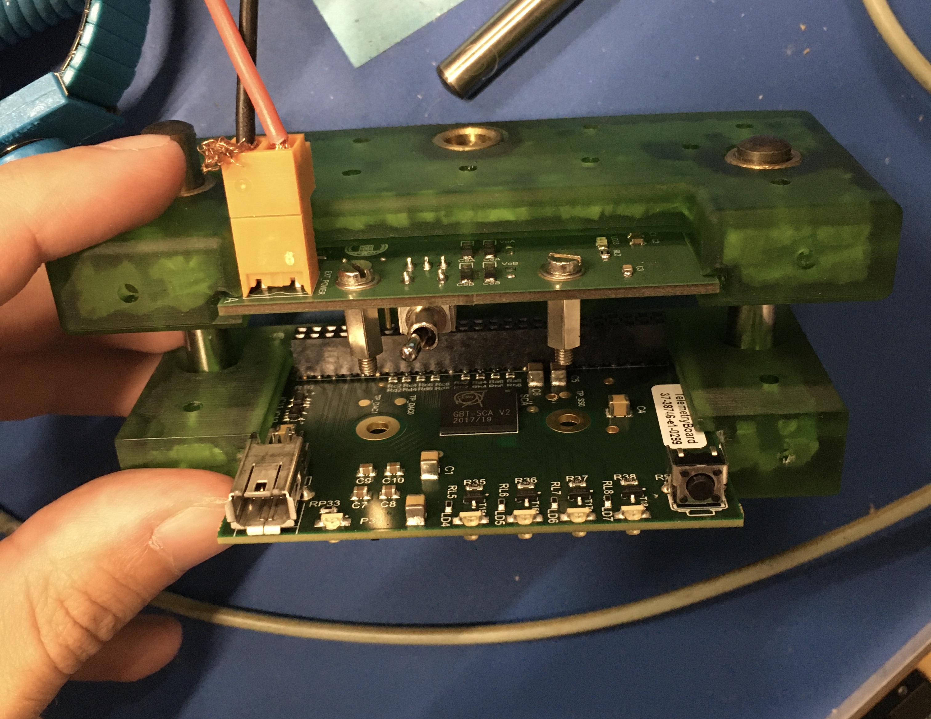
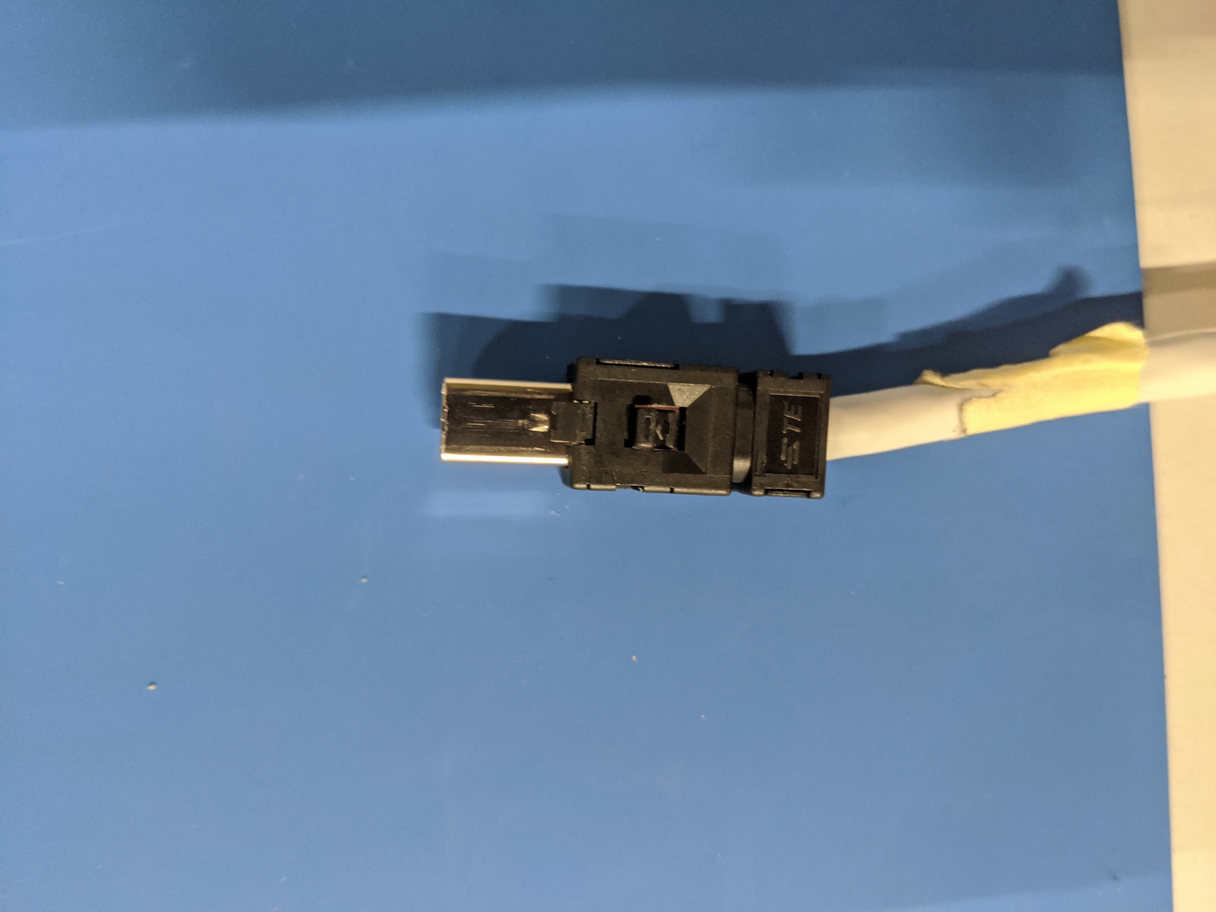
Take note of the TCM serial number and insert it into the testing apparatus (see image), ensuring to be careful to not break or bend any pins when closing it
-
Connect the TCM to the TCB via a Mini IO ethernet cable
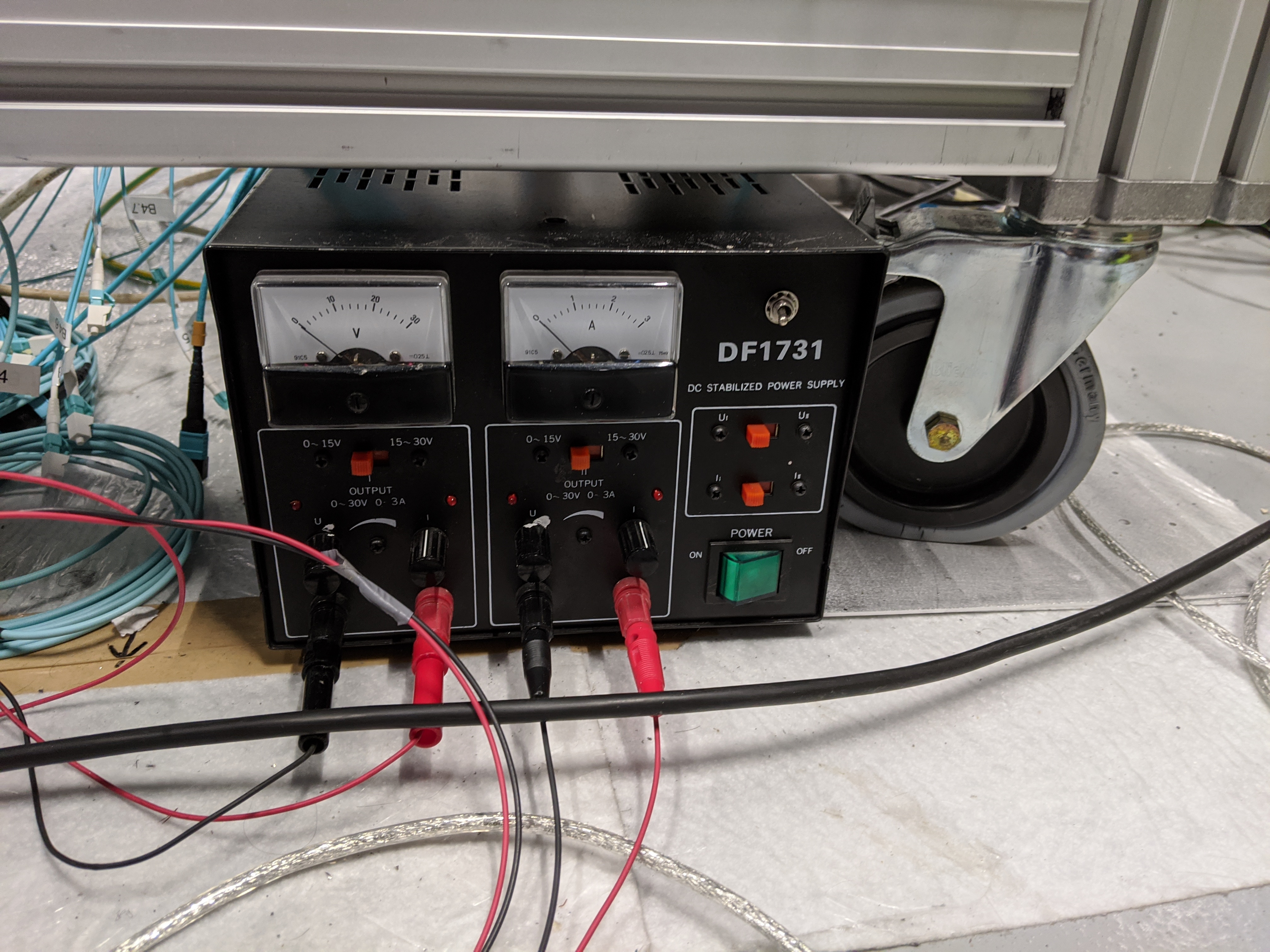
- Turn on the power supply
-
Get to the TCM QA panel (while connected to
lbminidaq2-17as for the DCB QA): runWCCOAui -proj UTLVTEST -m gedi &then locate and open the TCM QA panel (in the
panelsfolder). -
Enter the TCM serial number and then run the TCM QA by clicking Start Test
QA failure
The QA may fail for a number of reasons. As a general note, on any given panel, it is often a good idea to hit the Start Monitoring button, if it exists, especially if you have just altered/restarted something. Other potential fixes include:
- Check that you can detect the SCA where the Mini IO cable is connected (should be SCA 0) by opening up the TCB panel (there should be a button on the TCM QA panel to open this). If you cannot detect the SCA, you can try plugging into another slot on the TCB or try power cycling.
- If the TCM QA fails with a message that it failed at the "Configuring SCA" step, you can try power cycling, playing with the switches on the TCM (in case they weren't properly set), and restarting the GbtServ (
pkill -9 GbtServ). If none of this works, set the TCM aside with a note. - If the TCM QA fails with a message that it failed because "ADCs not connected" (or similar), set the TCM aside with a note including the feedback from the QA panel.
Proposed LVR nominal voltages
As discussed with Phoebe (but to be altered to account for sense current monitoring issue found while testing), the proposed voltage ranges for the LVR are
| LVR type | M VrsR | M VregR | S VrsR | S VregR |
|---|---|---|---|---|
12A | \(1.25 \pm 0.03\) | \(1.4 \pm 0.05\) | - | - |
12MSA | \(1.25 \pm 0.03\) | \(1.4 \pm 0.05\) | \(3.7 \pm 0.5\) | \(1.4 \pm 0.05\) |
12MS | \(1.25 \pm 0.03\) | \(1.4 \pm 0.05\) | \(3.7 \pm 0.5\) | \(1.4 \pm 0.05\) |
15MS | \(1.52 \pm 0.03\) | \(1.7 \pm 0.05\) | \(3.7 \pm 0.5\) | \(1.7 \pm 0.05\) |
25A | \(2.53 \pm 0.03\) | \(2.84 \pm 0.05\) | - | - |
Nomenclature
VrsR: Sense voltage (converted)VregR: Output voltage (converted)VisR: Sense current (read as a voltage, before conversion)
Note
- All voltages are in unit "V".
- These expected values are pre-set in the test panel as default valules, but they remain user-changeable.
- Since LVR CERN QA doesn't involve a load, all
VisRis assumed to be at \(0.1\). - In
12MSAcase, all expected voltages forAchannels is assumed to be the same as that of theMchannels. -
For slave
Schannels, the actual sense lines are unconnected. Instead,Master_Vref_Sense_inis connected.(See LVR schematic, p. 4)
-
For
Ssense lines, as long as it's notrail(5.5 V) orGND, we are fine with it.
Info
- The Output voltage
VregRis the voltaged measured at LVR output connector. - When sense line is unconnected, \(\frac{\text{Sense voltage}}{\text{Output voltage}} = \frac{2000 - 249}{2000} = 0.88\).
The LVR QA panel (use described here) will automatically adjust to test the voltages are within these ranges after the LVR type is set in the panel.
Update LVR firmware
-
Configure the LVR blue jumpers as shown in here:
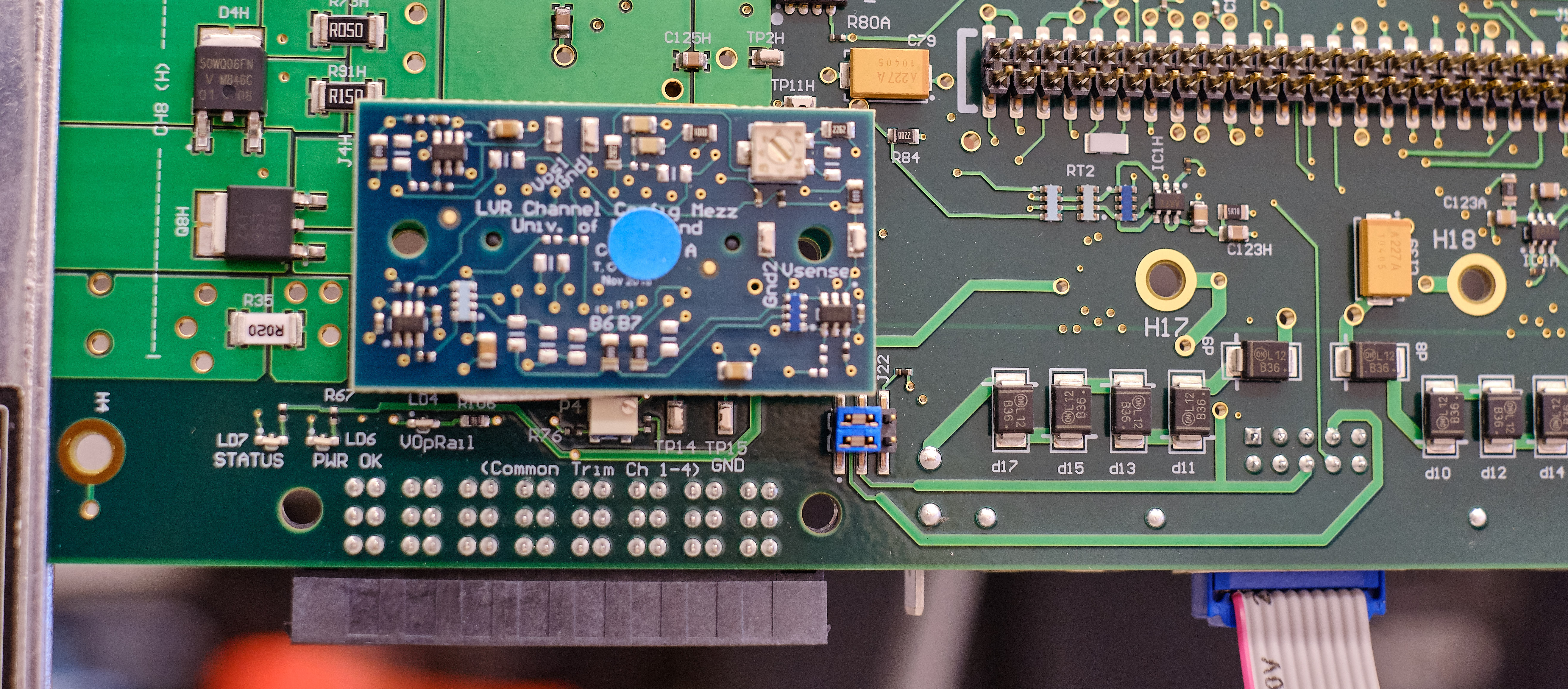
Note
These jumpers need to go back to their original positions after the firmware update. This is need to ensure some FPGA fail-safe is enabled.
-
Connect the LVR input BB and JTAG to LVR according to this picture, and turn on the power:
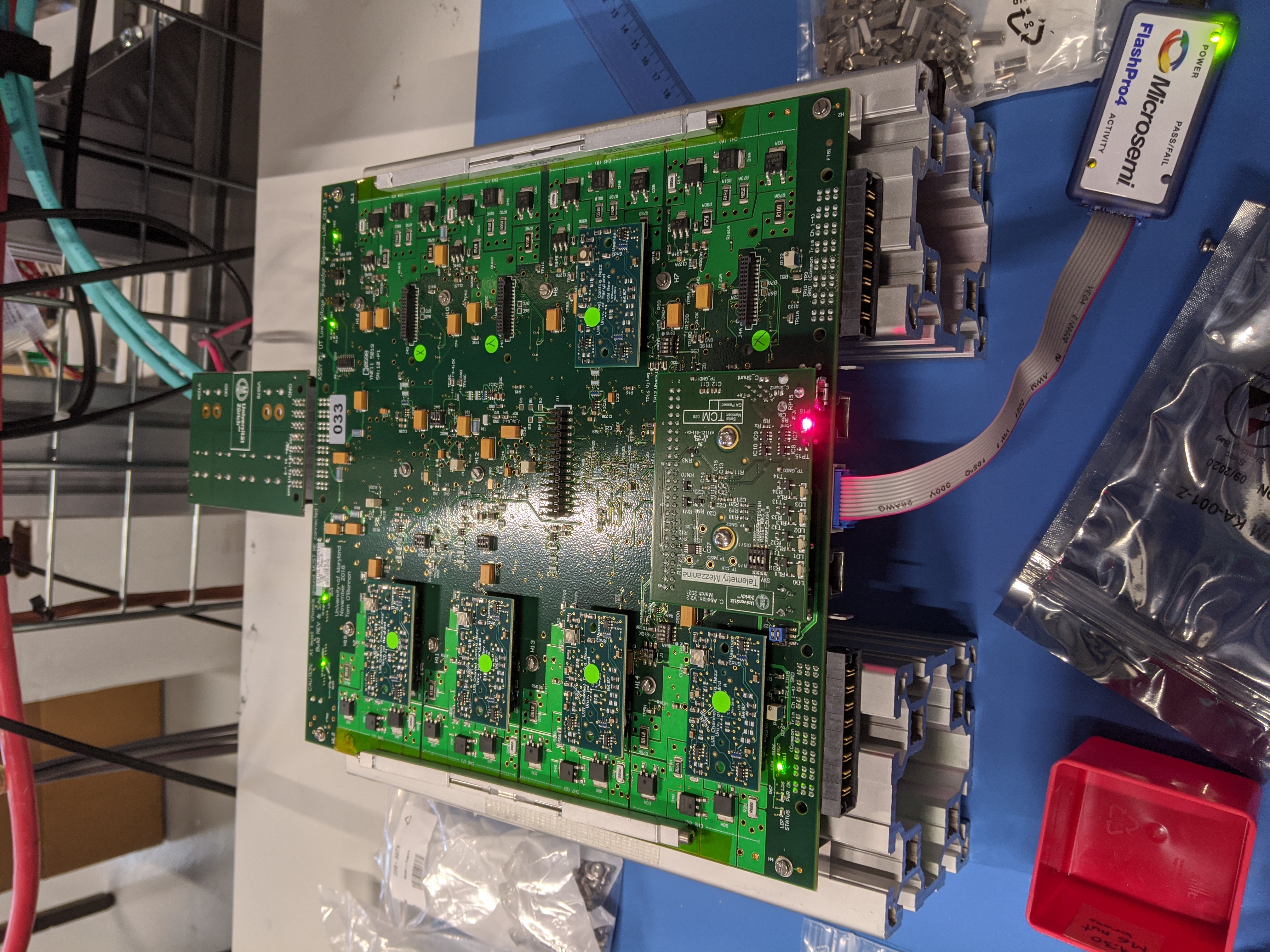
Warning
The GND shold not be connected during the firmware update process.
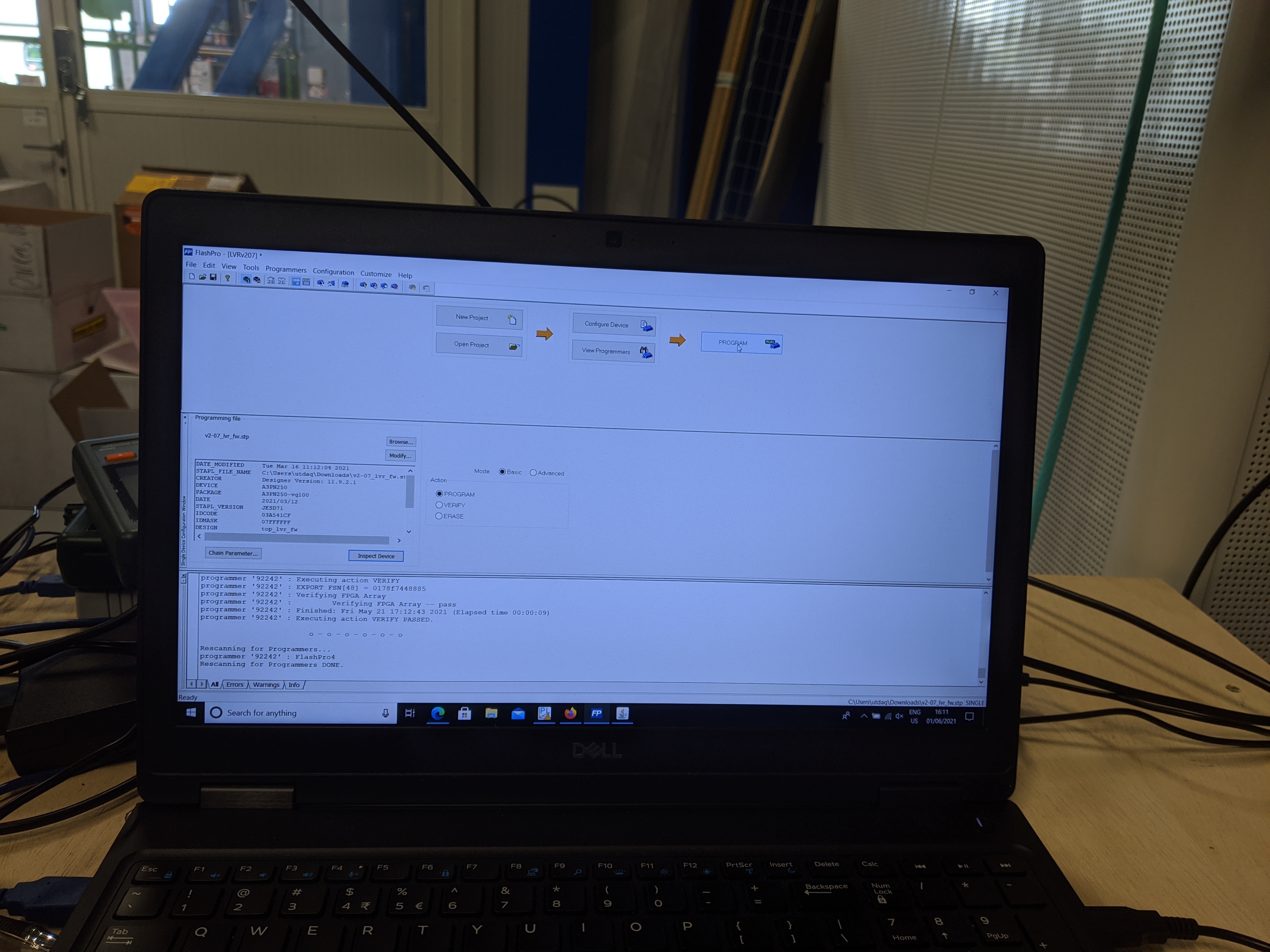
-
Use the nearby laptop to update the firmware. The flasher should have been opened already and all we need to do is click PROGRAM.
-
Once the firmware is updated, turn off the power and remove the input BB and the JTAG. Don't forget to put the blue jumpers back to their original position
Install TCM
-
Install the 10 mm standoff, with one washer at bottom and one at top (ie. two washers per standoff):
-
Align and install the TCM, with the Mini IO cable connected to it (and the TCB)
Use the LVR QA panel
- Connect all the CCMs on the LVR according to the board subtype
- Connect the GND to LVR. See the TCM standoff picture for GND connection.
- Re-connect the input BB, and turn on the power
-
Launch the LVR CERN QA panel in a terminal:
WCCOAui -proj UTLVTEST -p fwTelemetry/QA_LVR.pnl &Info
The panel looks like this:
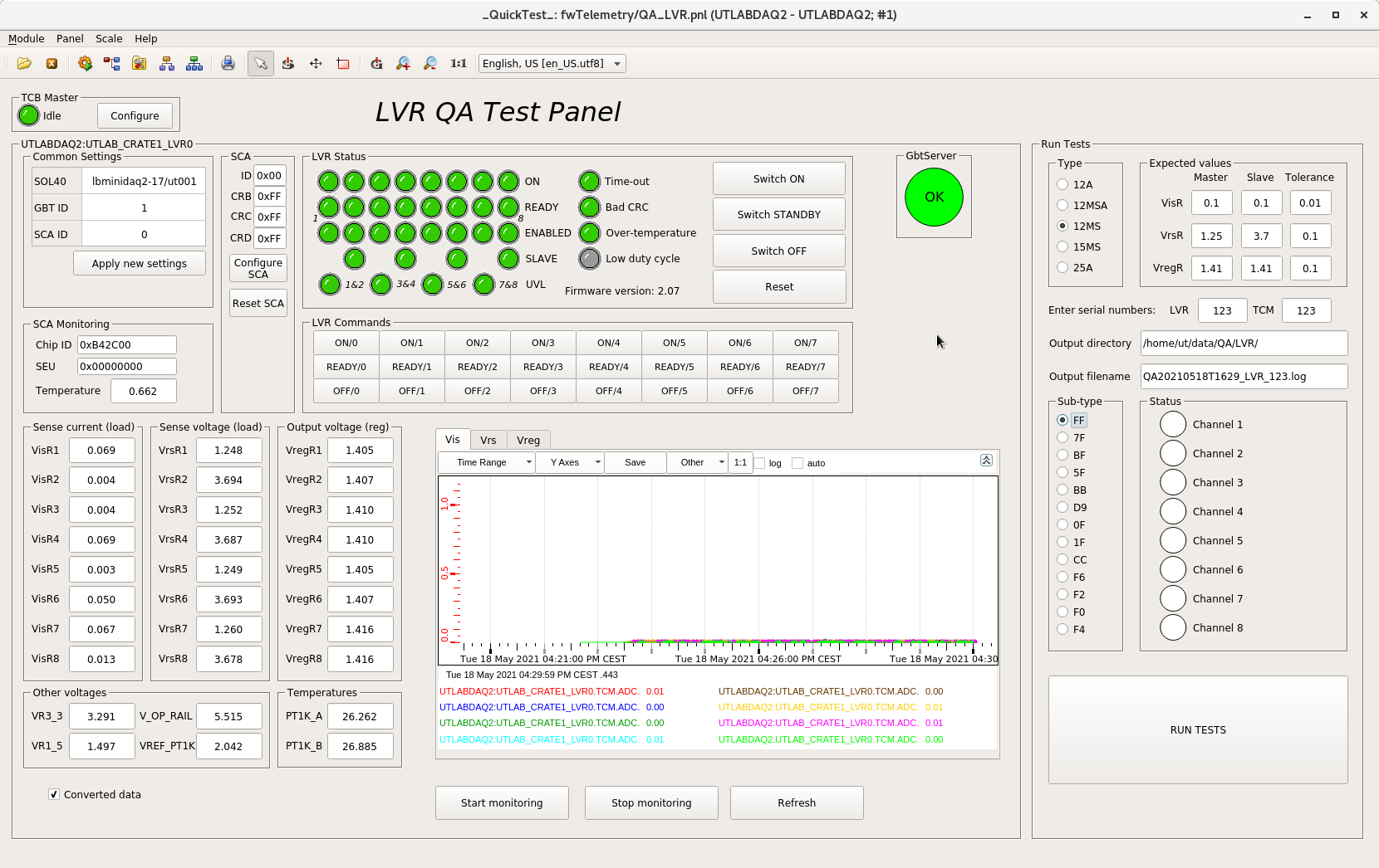
-
Input LVR and TCM serial number.
- Choose the correct LVR type and subtype.
- Click RUN TESTS
-
Assuming the board passes, turn the power off and disconnect everything, keeping the TCM and CCMs installed on the LVR
QA Failure because of high
VisWe have found that a handful boards seemingly "fail" because of an unanticipated issue caused by the TCM reference voltage being tied to GND. During the testing at UMD, the ref was tied to 1.5V, so the issue was not observed. Also, I believe the expectation is that when the LVR is connected to a load, regardless of whether the TCM is tied to GND, the high
Vis"issue" should go away (check this with Phoebe...).If you find a board that fails the QA because of one (or more) channels (say, channel
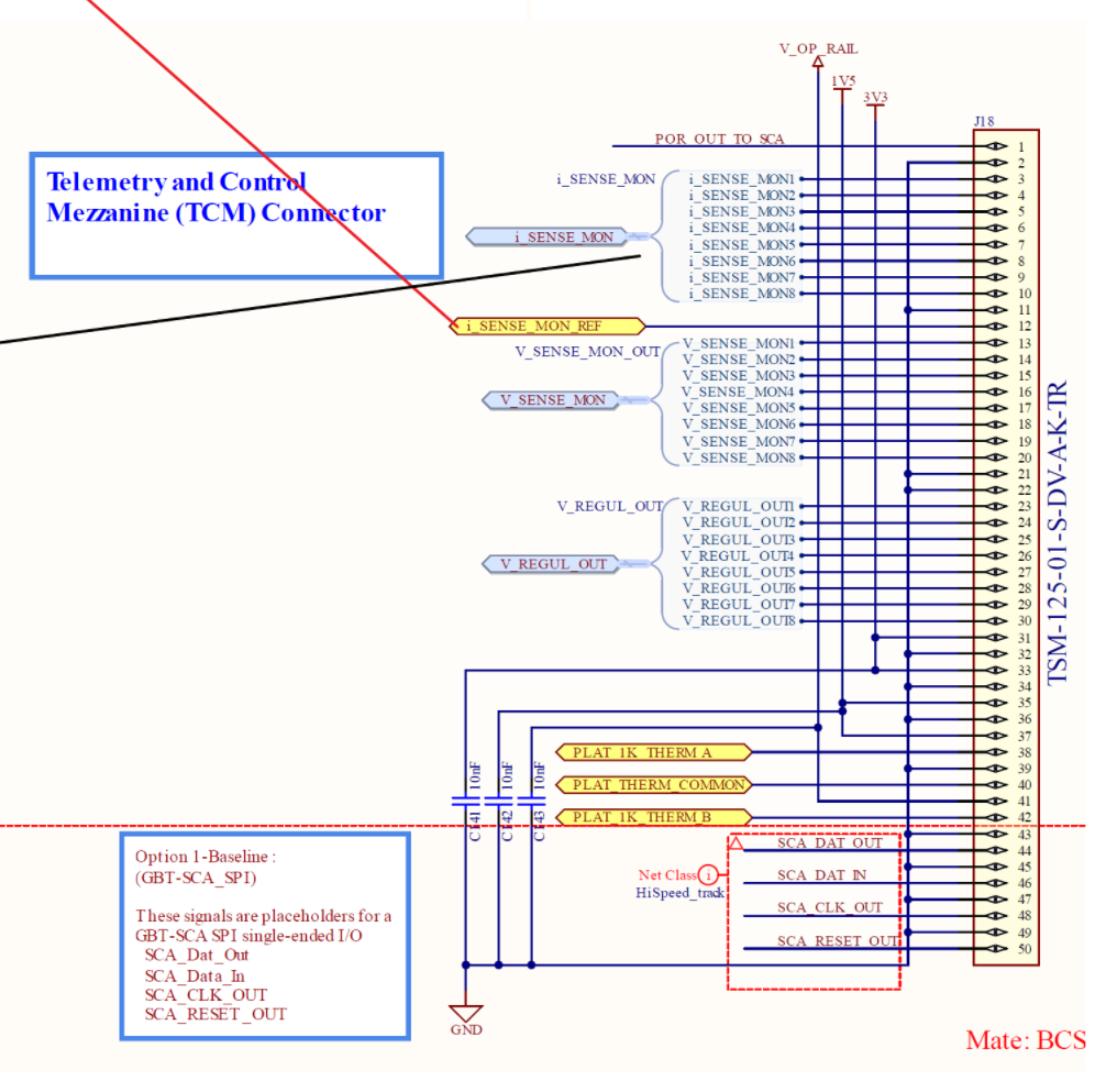
j) reading out a highVis, as long as you can verify the anomalous readings go away when the TCM reference is tied to 1.5V, you can pass the LVR. To do this, follow these steps:- With the LVR on and the TCM attached, just verify with a multimeter that the reading from the LVR QA panel is correct. To do this, first get an "unconverted" reading from the QA panel by unchecking the "converted data" checkbox, and note the "
Vis" value for the problematic channel (this is now in V). Then, referencing the TCM schematic below, probe (on the solder pads on the TCM) betweeni_SENSE_MONjandGND(say, pin 2). This voltage readout should match what is reported in the QA panel. Note that we "expect" (based on experience) this voltage to be <60mV. If it's larger, check with Phoebe before proceeding. - Next, turn the LVR off and remove the TCM. As in the initial QA at UMD, turn on dip switch 1 on SW5 (on the back of LVR). Turn the LVR back on. You will now connect, using a wire between LVR pin pairs that connect to the TCM, pin 12 (
i_SENSE_MON_REF) to another pin and then again probe betweeni_SENSE_MONjandGND. First, as another sanity check, connect pin 12 toGND(say, pin 11); probing betweeni_SENSE_MONjandGNDshould return the same voltage reading as above. Second, connect pin 12 to 1.5V (say, pin 35). You should now see (to within a few mV) 1.5V when probing betweeni_SENSE_MONjandGND. - If this all works correctly, you can pass the LVR, but put a note in the UMD database. Also, turn off dip switch 1 on SW5 and reinstall the TCM before putting away the LVR.
Warning
There's a latch that needs to be released manually when trying to unplug the Mini IO cable.
- With the LVR on and the TCM attached, just verify with a multimeter that the reading from the LVR QA panel is correct. To do this, first get an "unconverted" reading from the QA panel by unchecking the "converted data" checkbox, and note the "
-
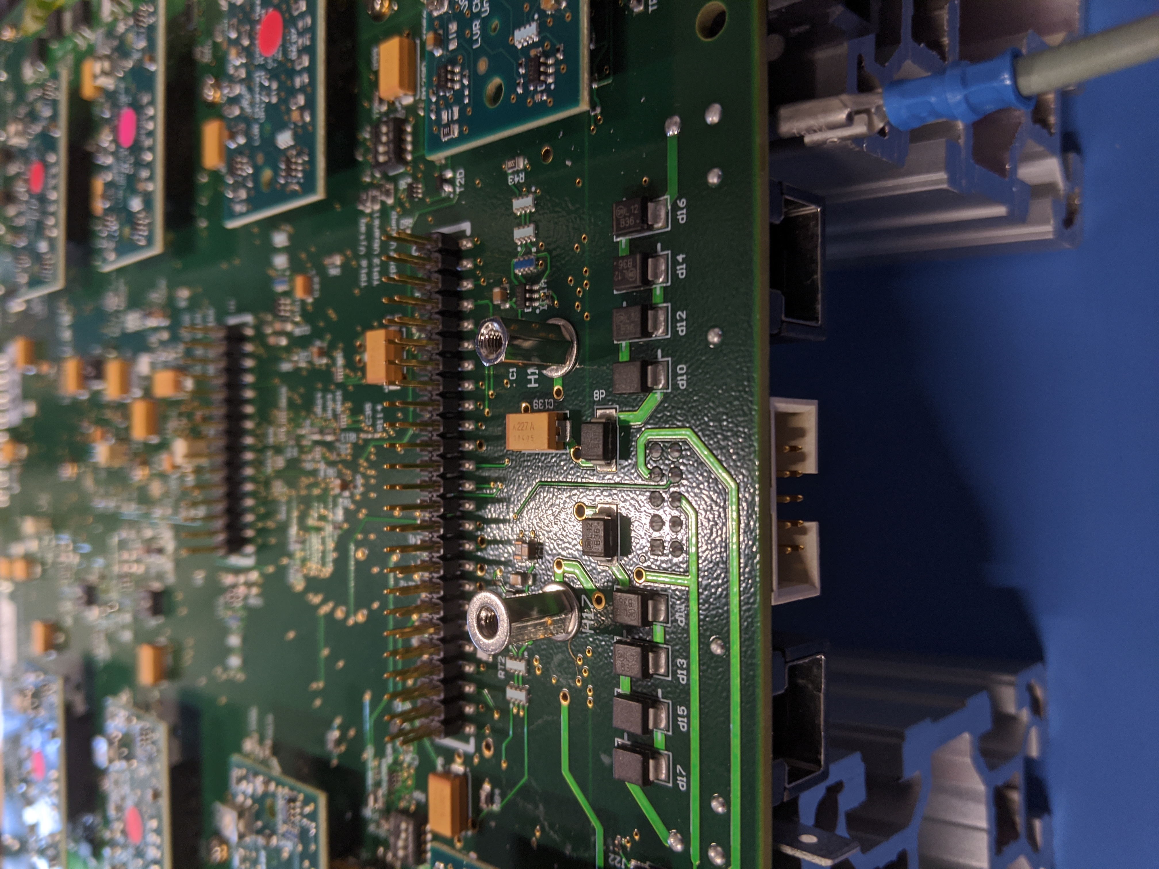
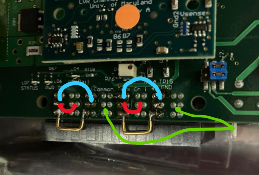
In the case of an LVR with MS channels, test that the soldering was done correctly using a multimeter. Note that the sets of 6 pins in the image below should all be at the same voltage. With the multimeter, probe the resistance between the indicated blue, red, and green lines. The blue tests that the soldering was successful (expect a reading near 0 Ohm), the red tests that the soldering didn't damage anything (expect a reading near 80 Ohm), and the green tests that the LVR power and chassis GND are still isolated (expect a reading >=25 kOhm).
Installing LVR to SBC
- Check that CCMs and TCM are properly installed and sit flat
-
Make sure the wedgelocks are loose, and slide the LVR into the SBC
-
Make sure the wedgelock is locked with specified torque of 80 cNm (7 inch-ft).
Info
- The name of the LVR wedgelock is Birtcher wedgelock retainer (40-5-12-T)
- The data sheet of the wedgelock can be found here
-
Test the isolation of
GNDandGND_earthafter connecting theGND_earthcables from SBC to LVR.Info
This can be done with a multimeter. Fix one probe on SBC, while use the other end to probe on the right-most pin of the right LVR output connector (see picture below).
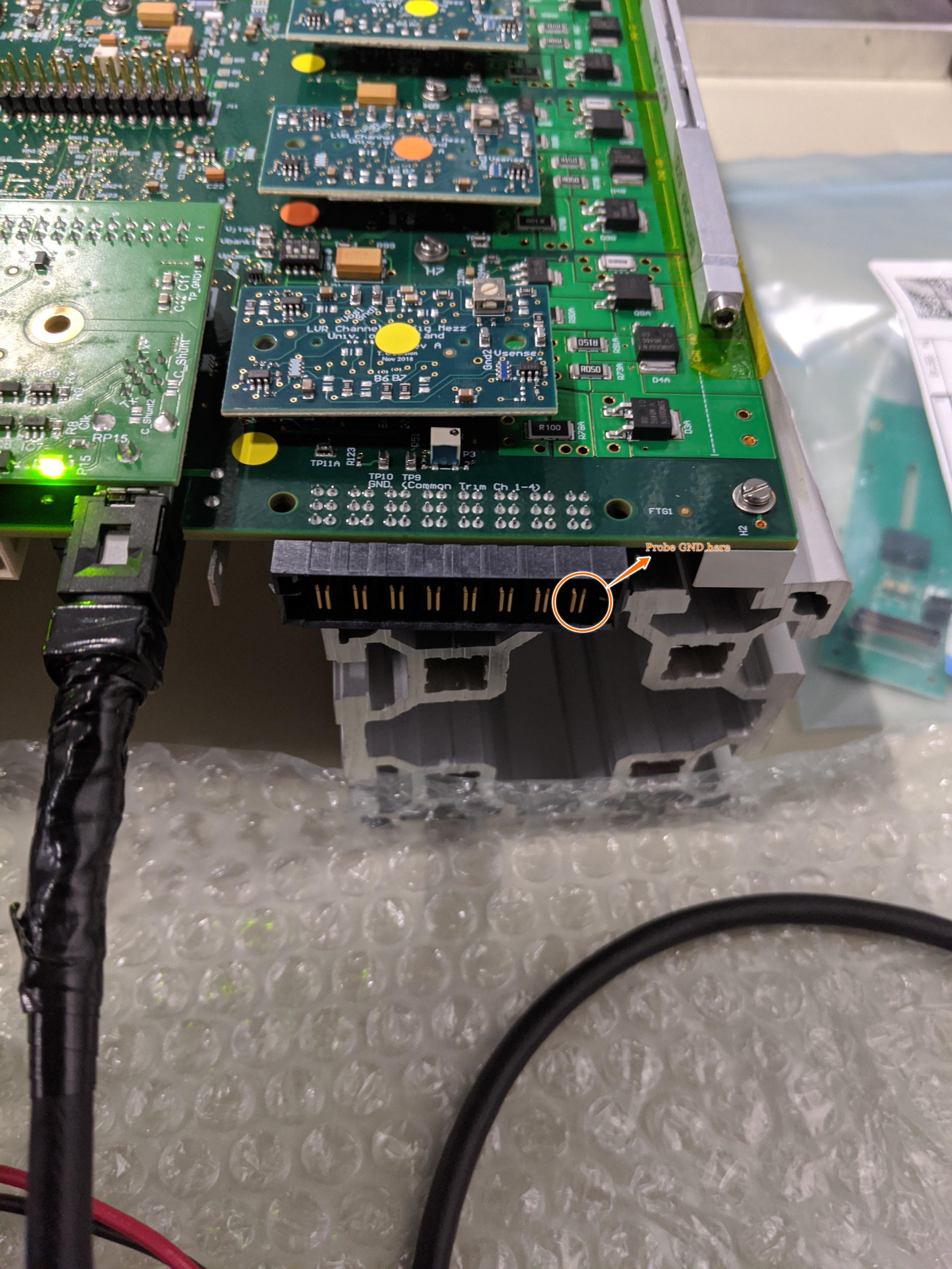
One LVR only needs to be probed once.
Info
The
LV_RETURNis connected toGNDon LVR, but not theGND_earth.