DCB mechanical assembly
For a summary of tasks, if you're already familiar with the assembly procedure, see here.
Tip
It is generally much quicker to work on multiple boards in parallel. After getting used to the assembly procedure, when working in parallel it should generally take around 1 hr/board assembly (assuming no slow-downs due to missing parts, etc).
Info
Most of the equipment needed for assembly should be able to be found on the downstairs table at any given moment. The new DCBs should be in boxes under that table, and new backplates, heat pipes, and thermal fillers should be in boxes nearby. The optical mezzanines are placed in a labeled grey cabinet, while the VTT/Rxs are in a black cabinet (all downstairs).
Thermal gap filler installation
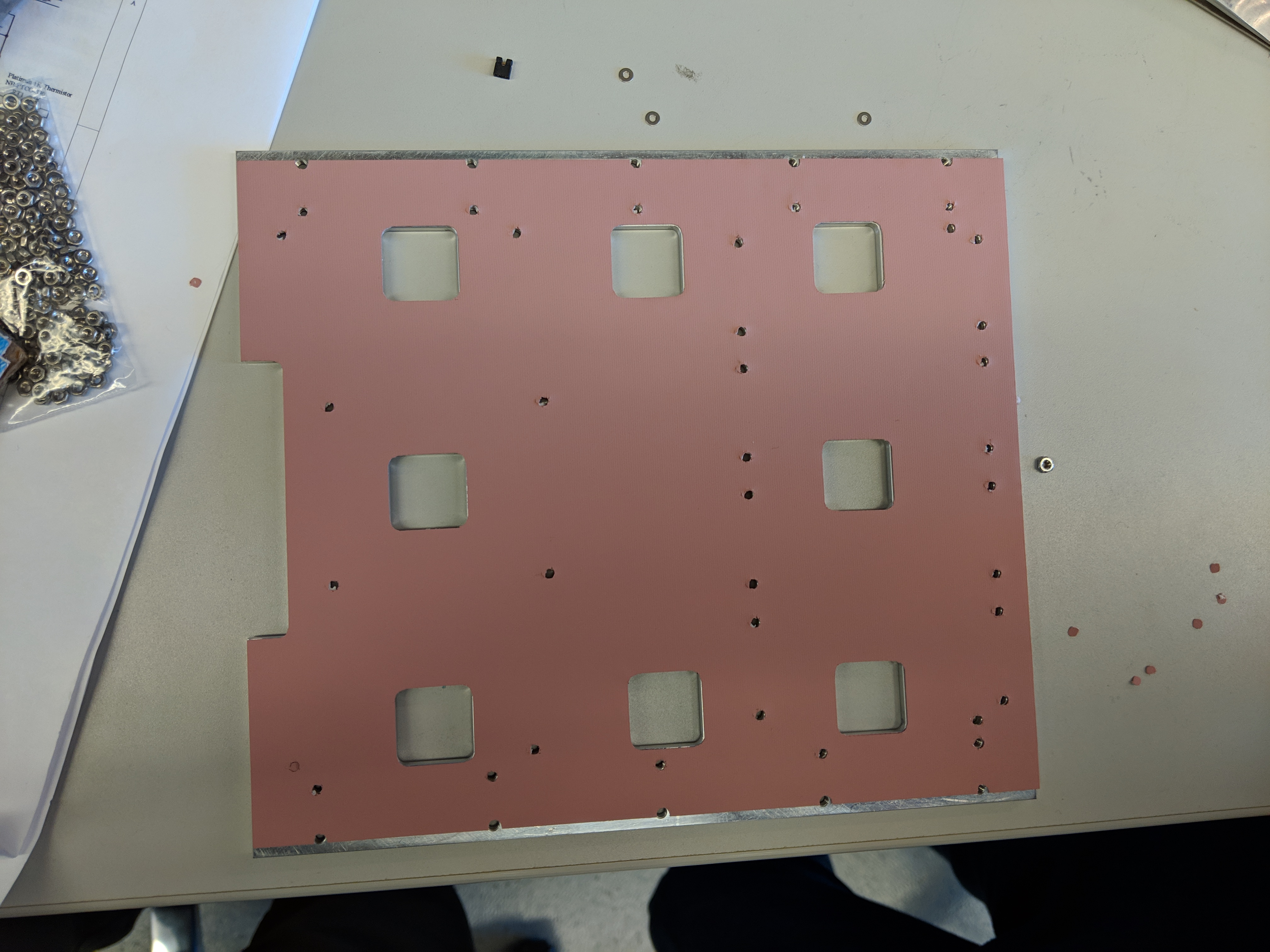
There are pre-cut thermal fillers for the DCB backplate. Peel the film off and put it on, making sure that the pre-cut holes align with the holes of the DCB backplate. It is much easier to ensure the thermal gap filler is straight if two people work together, or if working alone, it makes it easier if you only partially remove the film, position the thermal filler on the backplate, and then slowly peel off the rest of the film while letting the filler fall flat into place on the backplate.
Warning
Make sure that the thermal gap filler is placed on the flat side of the backplate.
The backplate is not symmetrical. The thermal gap should be put on the side that doesn't have countersunk screw holes.
Once the thermal gap filler looks straight, use a screw to take out any leftover thermal gap filler over the screw-holes that may have not been trimmed off. This will ensure that the backplate will connect smoothly to the DCB and that no residue from the thermal gap filler will attach to the DCB.
Heat pipe installation
To install the heat pipes:
-
Put a thin line of thermal grease on the pipes using a spreader, not going all the way to the edges. The grease squeezes out when the pipes are installed and tightened. You can use the plastic spreader to even out the thermal paste.
-
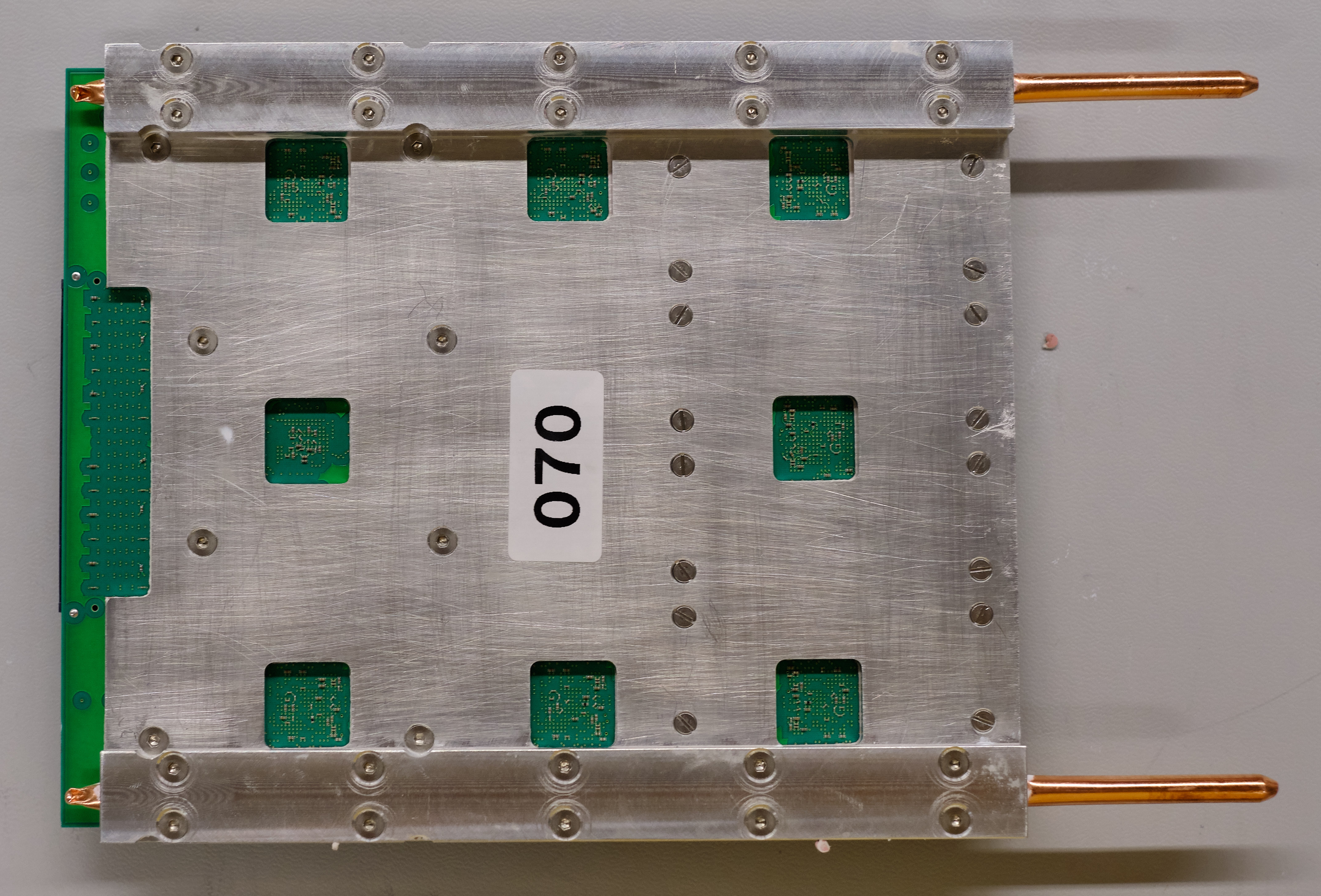
Use 10 M.3 countersunk bolts to secure the heat pipe to the backplate. Note that it is easiest to screw in opposite diagonal bolts first to fix the heat pipe. Note the orientation of the heat pipe in the image below
-
Wipe away excess grease along the sides of the heat pipe. Can use Isopropyl Alcohol to clean residue if needed (above 70% IPA).
-
Repeat for the second heat pipe.
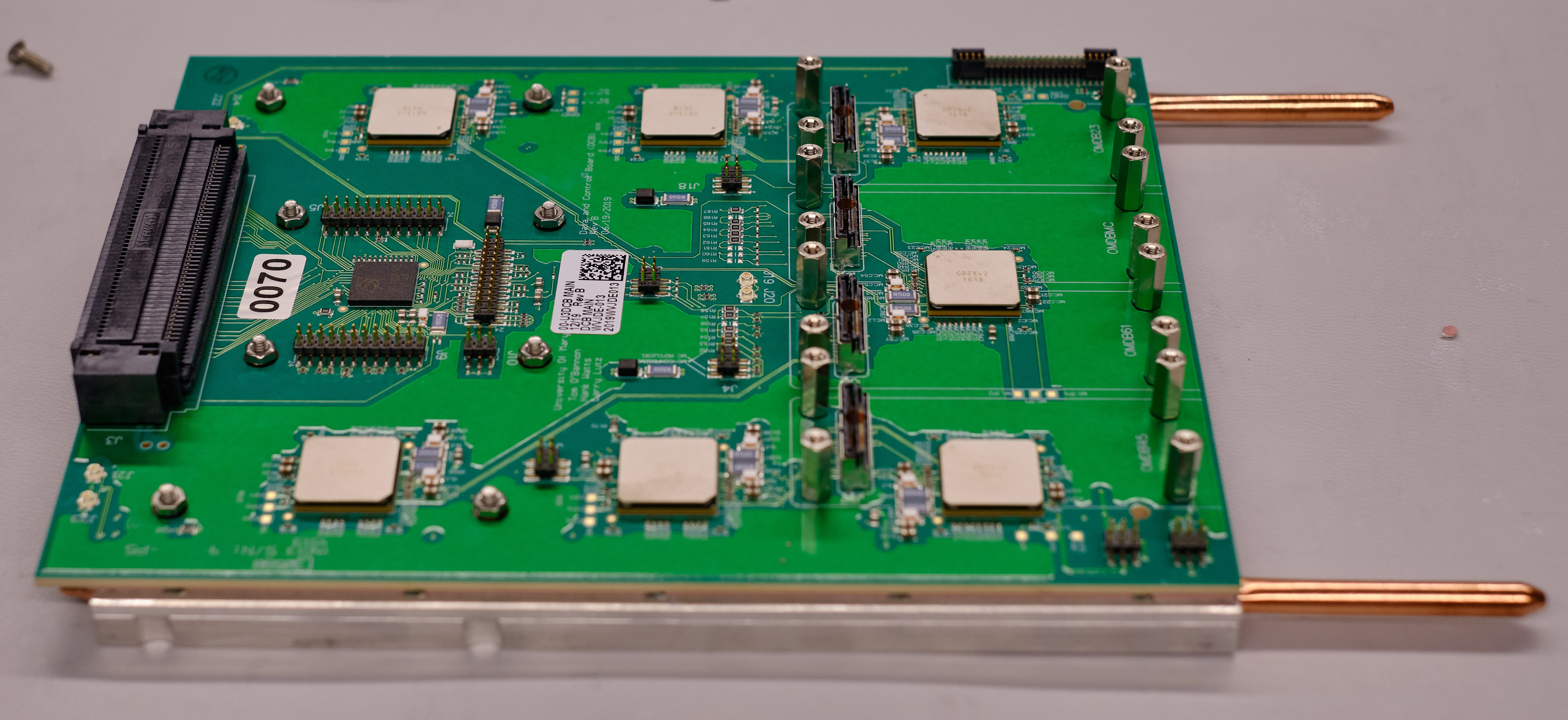
Place a numbered sticker in the center of the backplate, as shown (note the first image is a fully assembled DCB; you won't have the board screwed in yet). Follow the pictures below for further guidance or if anything is not clear.
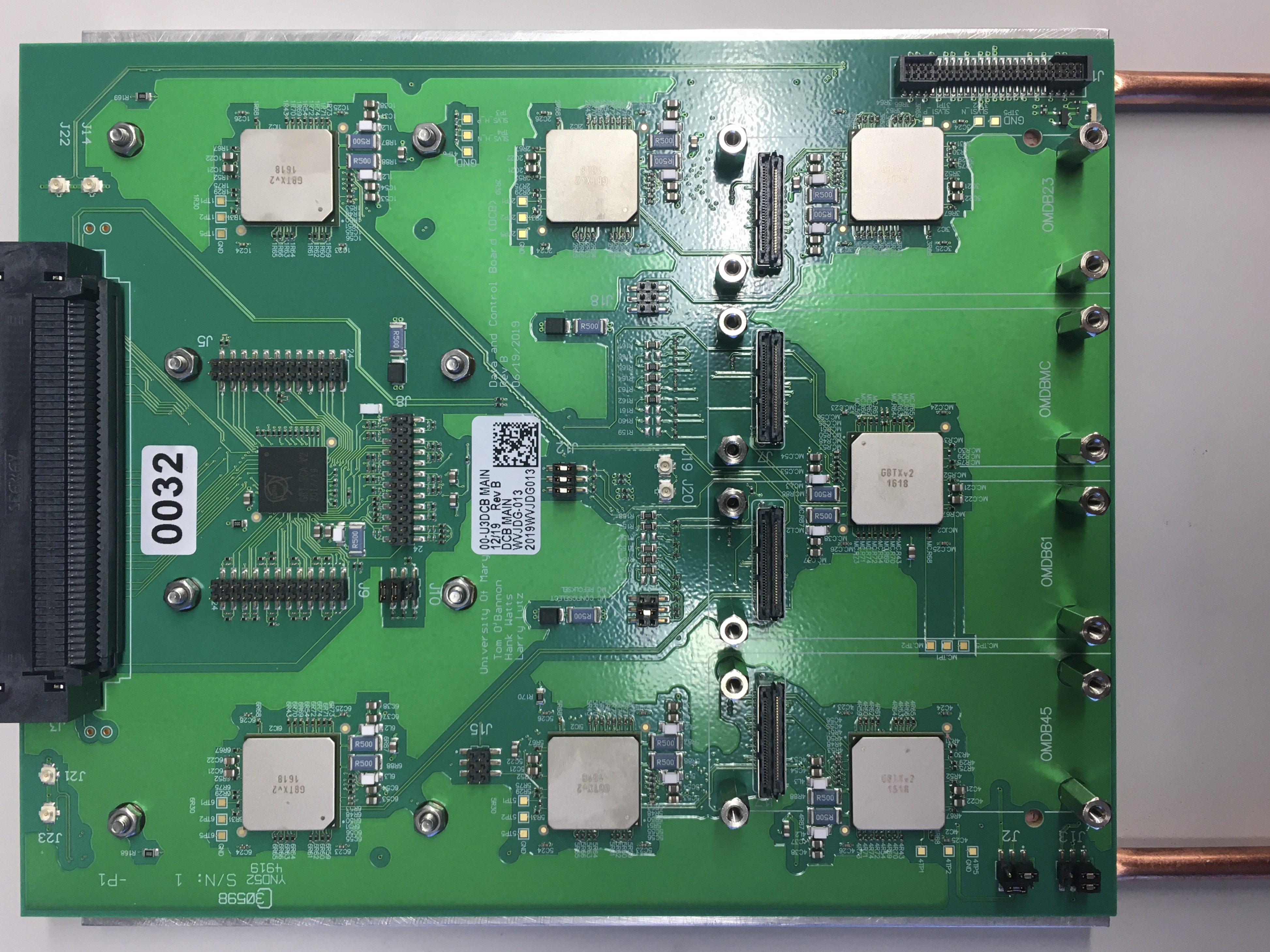
Inspection of new DCB
Warning
Make sure you are grounded at all times when handling the DCB!!
-
Look for scratches, gouges, and any other signs of obvious damage on the surface of the DCB.
-
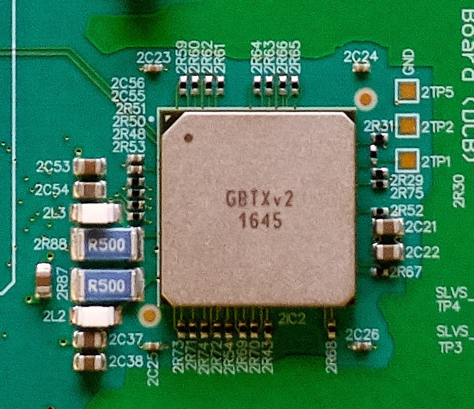
Inspect more thoroughly by focusing on 1 GBTx cluster at a time. All clusters should be the same and include the same components. If a piece appears to be missing, compare to the other groups. If they are all the same, it is likely correct
- Look for any pieces that are bent, broken, or otherwise askew within each cluster.
Note
Each GBTx has a marked corner which must match a white dot on the DCB. The black SCA also has marked corner and dot.
Note
There are also a couple small components, the ones next to pieces labeled "R500", with faint white lines on one side. That side also points to a white dot on the DCB
The dots are on the top left in this example
-
Now look at the 4 mezzanine connectors (the connectors inside the outline). Angle the DCB to see each pin clearly and confirm there are no globs of solder possibly connecting two pins. Also confirm that no pins are bent or broken.
-
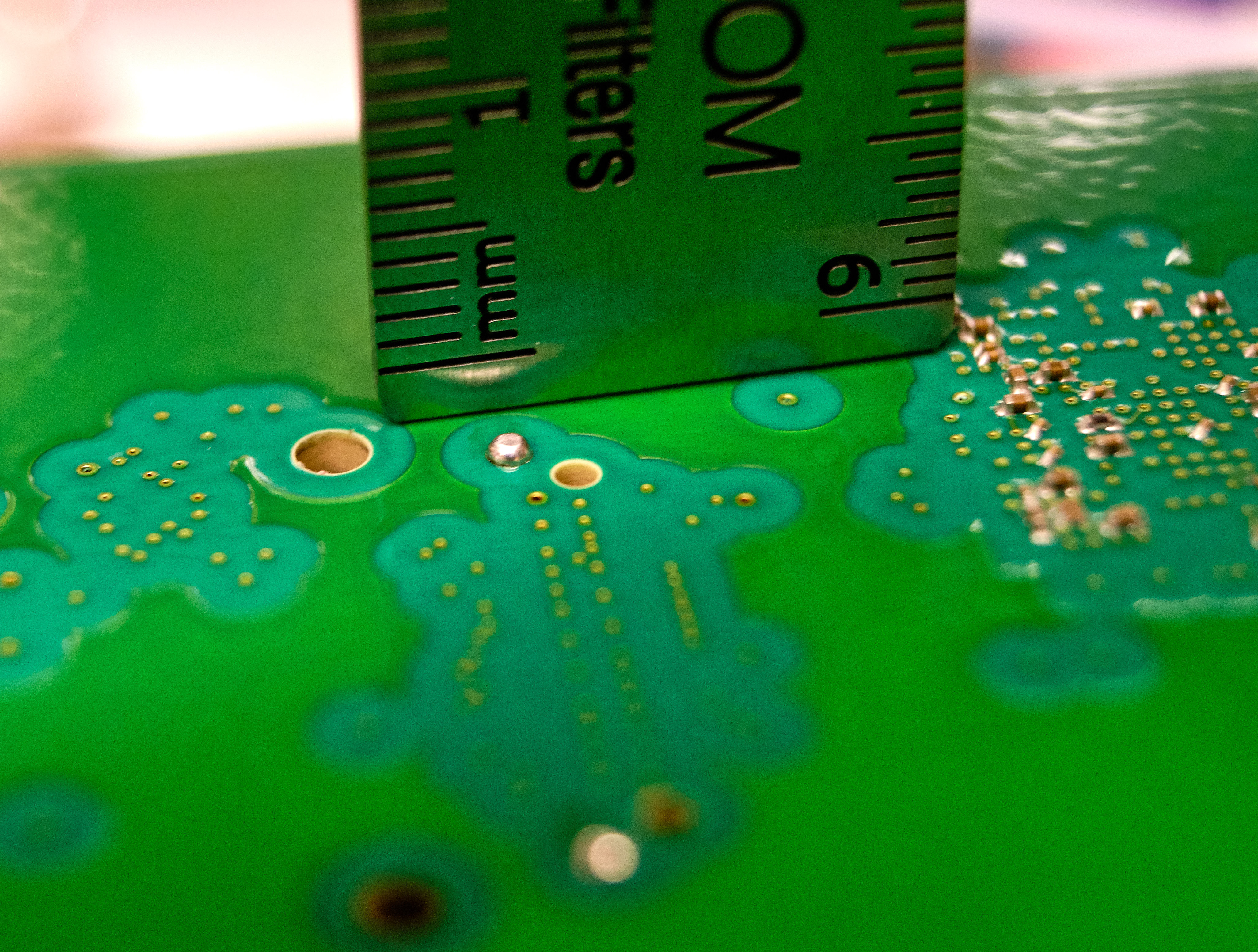
Next flip the DCB over so that you are looking at the bottom side of the DCB. Check the bottom side near the optical mezzanines to ensure that there are no extra globs of solder protruding through the surface of the DCB.
Note
If there are extra globs of solder present then it can short the DCB when assembled to the backplate.
An example of the extra globs of solder is shown here
-
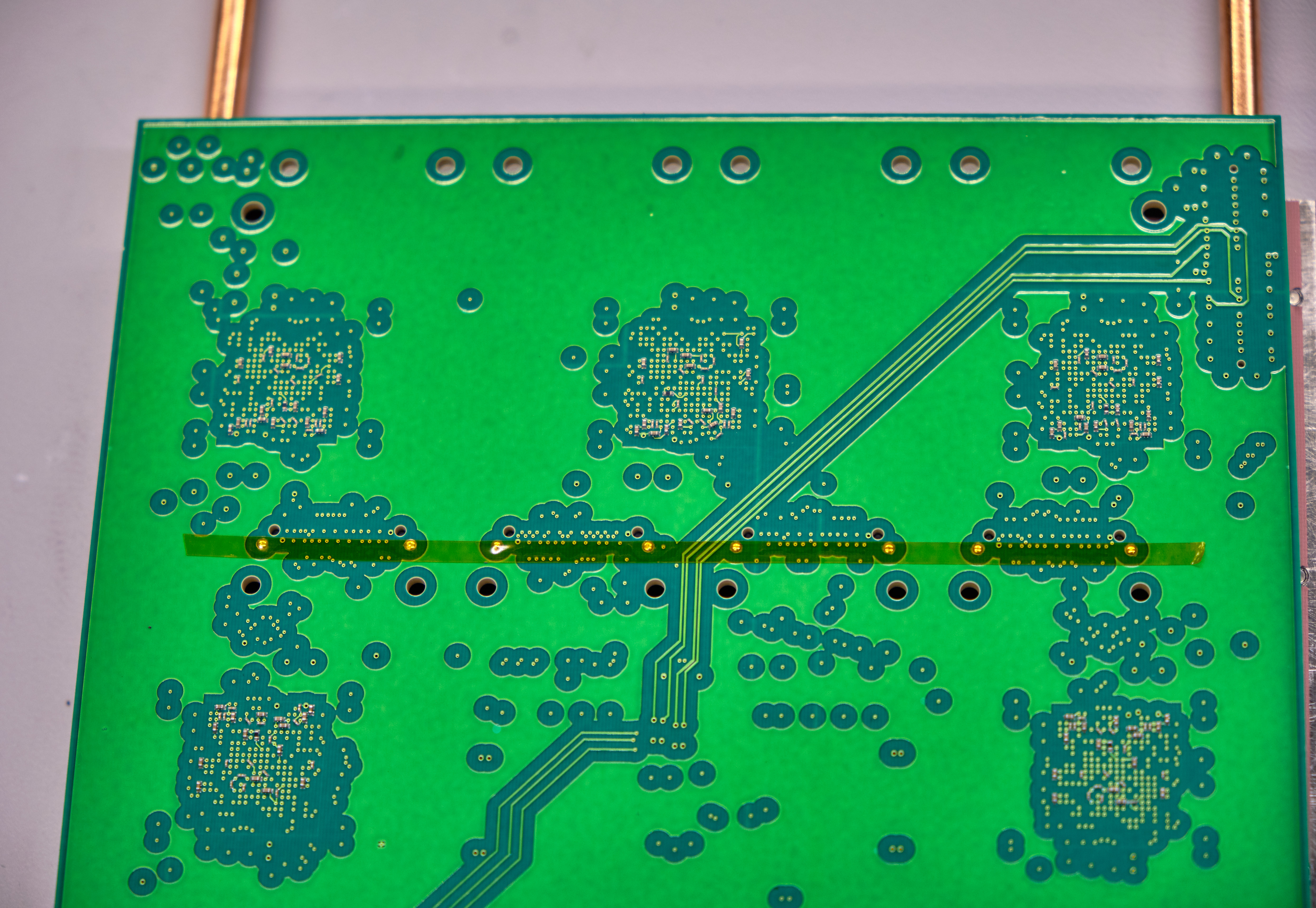
Place Kapton tape on solder pads, as shown in the image below (regardless of whether the pads seem to have excess solder). If any other excess solder globs are present, similarly place Kapton tape on them.
-
Finally examine the large backplane connecter on the other end of the DCB.
- Look into the connector at the pins and make sure they are all uniform. A bent pin could break a backplane.
- Tilt the DCB to look between the board and the connector. It is attached by many small solder pads so must lay flat and straight. Any angle or disconnected pads should be noted.
-
Place a small sticker near the backplane connector (again, the image below is of a fully assembled DCB; it's just meant to demonstrate the placement of the sticker)
Final board assembly
Tip
There are a lot of screws for this step. In addition to the continuity check to ensure the board and backplate aren't shorted after screwing everything in, it is likely a good idea to check the grounds are isolated after only screwing in a few screws. This may save you the time of unscrewing/re-screwing everything if the board and backplate are shorted.
Tip
After tightly screwing in a few screws and testing ground isolation, in general it probably saves time to loosely screw everything in first and then tighten later.
-
Use 16 M.2.5 countersunk bolts along with 16 long ("standoff") M.2.5 hexagonal nuts and Kapton washers (part# 5611-33-5) to install the DCB backplate onto the DCB and provide supports for the optical mezzanines. The bolts should be placed on the backplate side and should fit into the countersunk holes while the nuts and washers will sit on top of the DCB. Again fix opposite diagonal bolts first.
Note
This is for the flat edge/long pipe side of the assembly.
Warning
The nuts on top of the DCB should not be rotated as they will damage the surface of the DCB. In order to prevent this secure the nut using pliers or a socket wrench and use a screwdriver to tighten.
-
Use 8 M.3 countersunk bolts along with 8 short M.3 hexagonal nuts and Kapton washers (part# 5611-130-5) to secure the notched side of the backplate. The washers should be placed on the DCB to protect it from the hex nut.
Warning
The nuts on top of the DCB should not be rotated as they will damage the surface of the DCB. In order to prevent this secure the nut using pliers or a socket wrench and use a screwdriver to tighten.
-
Install jumpers to the board according to the picture, these are needed to configure the DCB.
- They should be oriented with their metal side away from the board
Red Lines are where the jumpers go
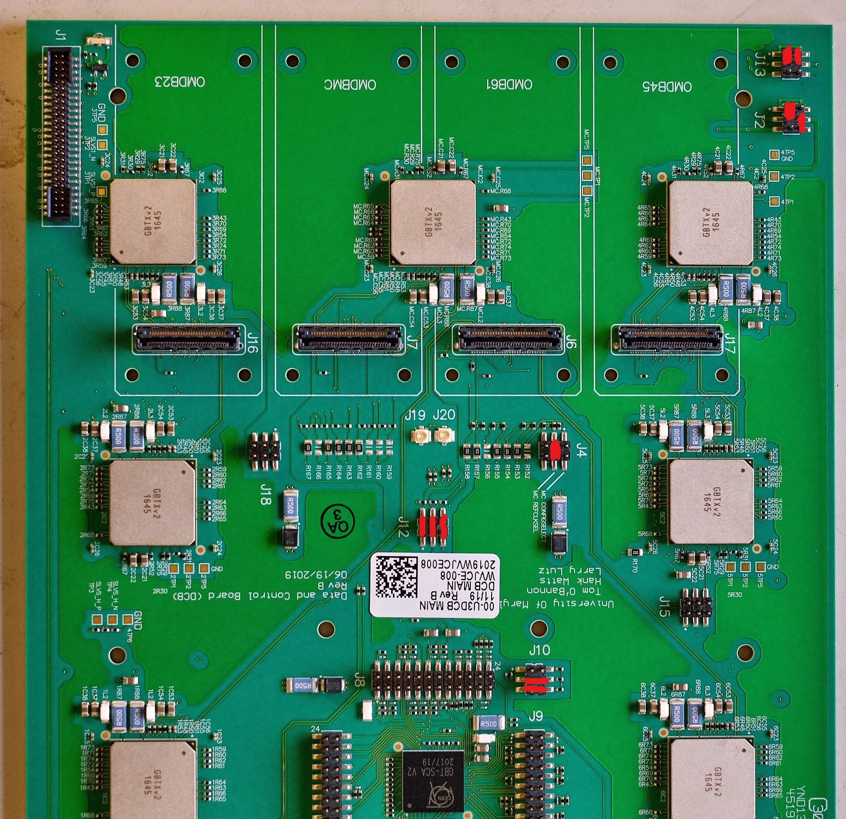
Note
You should install 10 jumpers to the following connectors:
J2pins 1-3, 4-6J4pins 3-4J10pins 3-4, 5-6J121-2, 3-4, 5-6J131-3, 2-4
Continuity check
Measure the resistance between any of the TP5 around the data GBTxs and the aluminum backplate. The resistance should be very large to ensure the backplate is not electronically connected to the DCB.
Optical Mezzanines
Each DCB needs 4 optical mezzanines, 3 with VTTxs and 1 with a VTRx. An assembled mezzanine will look like this, where the black component in a yellow casing is a VTTx. 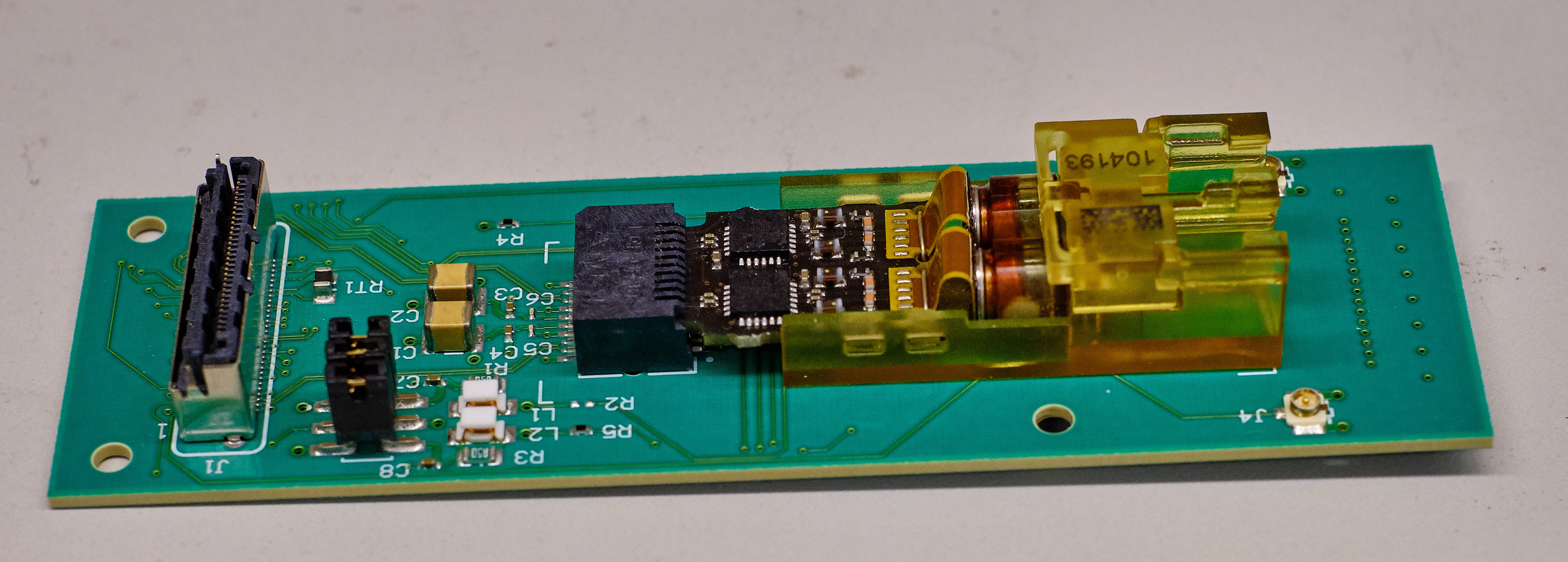
Note
A VTTx is black while a VTRx is red. They both have a yellow casing and look the exact same otherwise.
-
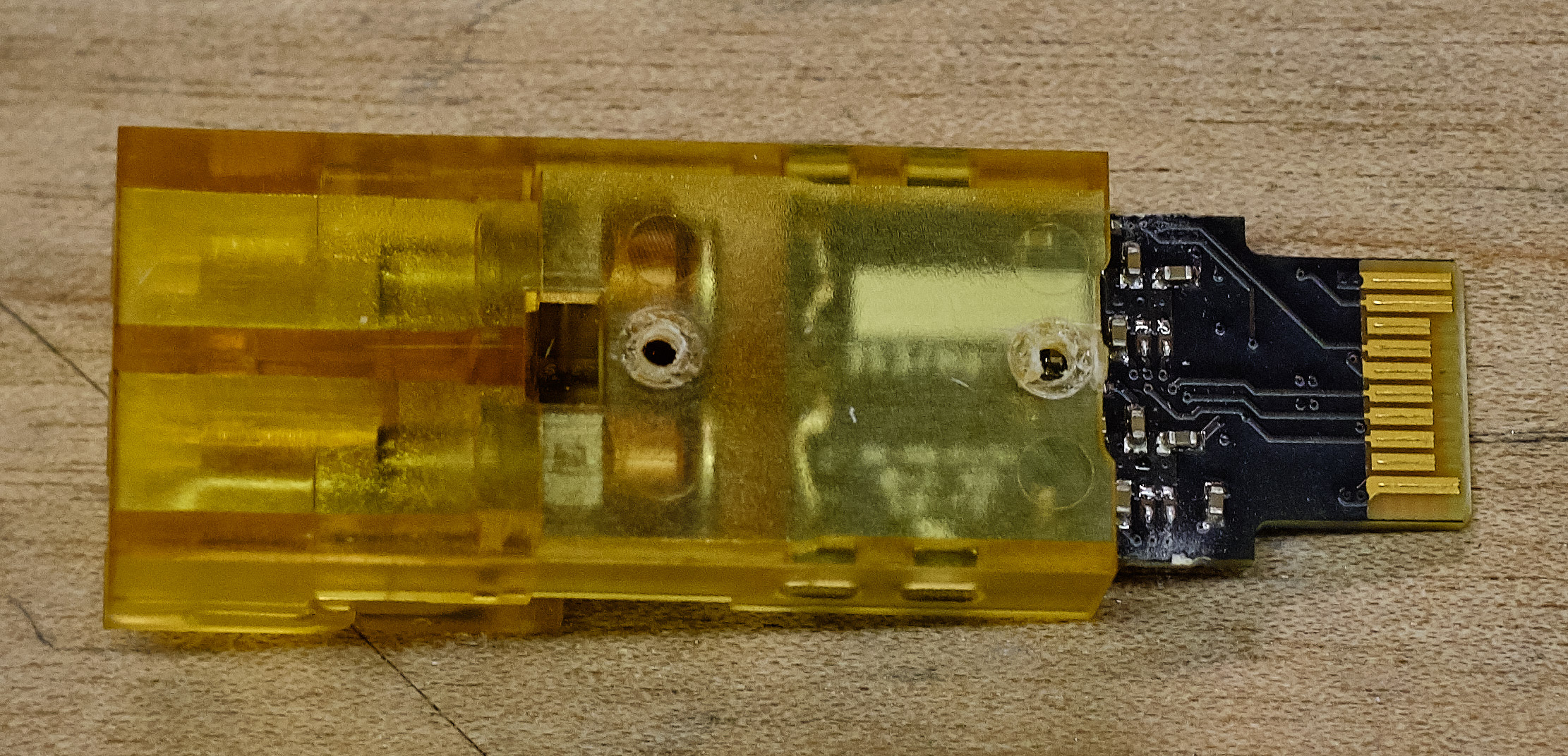
The VTT/Rxs have nubs on top that don't fit into the slot on the mezzanines. Take a pair of wire cutters and clip them off to be flush with the rest of the plastic casing.
- this can cause the holes to close over with plastic. Take a metal pick and carefully clear out the residual plastic to make a clean hole.
- this can cause the holes to close over with plastic. Take a metal pick and carefully clear out the residual plastic to make a clean hole.
-
Plug in a VTT/Rx and make sure the holes are aligned with the slot on the mezzanines front
-
Screw in 2 M1.4 bolts to attach the mezzanine and the VTT/Rx, tighten gently.
- It can be really hard to get the tiny bolts to work. If you're having trouble, use tweezers to hold the bolt in place while putting a decent amount of force into the hole while you start to screw it in
-
Repeat for 4 total mezzanines. Make sure one has a red VTRX while the rest have VTTxs
Update database
You've assembled a DCB! Record the sticker serial number to the database. Place assembled board back in ESD bag and bubble wrap, and put in box with other assembled DCBs (may be upstairs near the initial QA setup). Place assembled mezzanines back in ESD bags, and put them upstairs in a box near the initial QA setup. Don’t throw out the bubble wrap for the mezzanines; it’ll be used for shipping. Put it back on top of the cabinet with all the new optical mezzanines.