CCM Test Stand Configuration
Configuring the CCM test stand is a 3 staged process. This involves configuring the test stand based on if the CCM being used is 12, 15, 25, and MS or A.
Stage 1: Load Board
The first stage involves selecting the appropriate output board to plug into the LVR output. There are two different output boards:
-
For
MSCCMsOutput board for
MSCCMs, and where to plug it in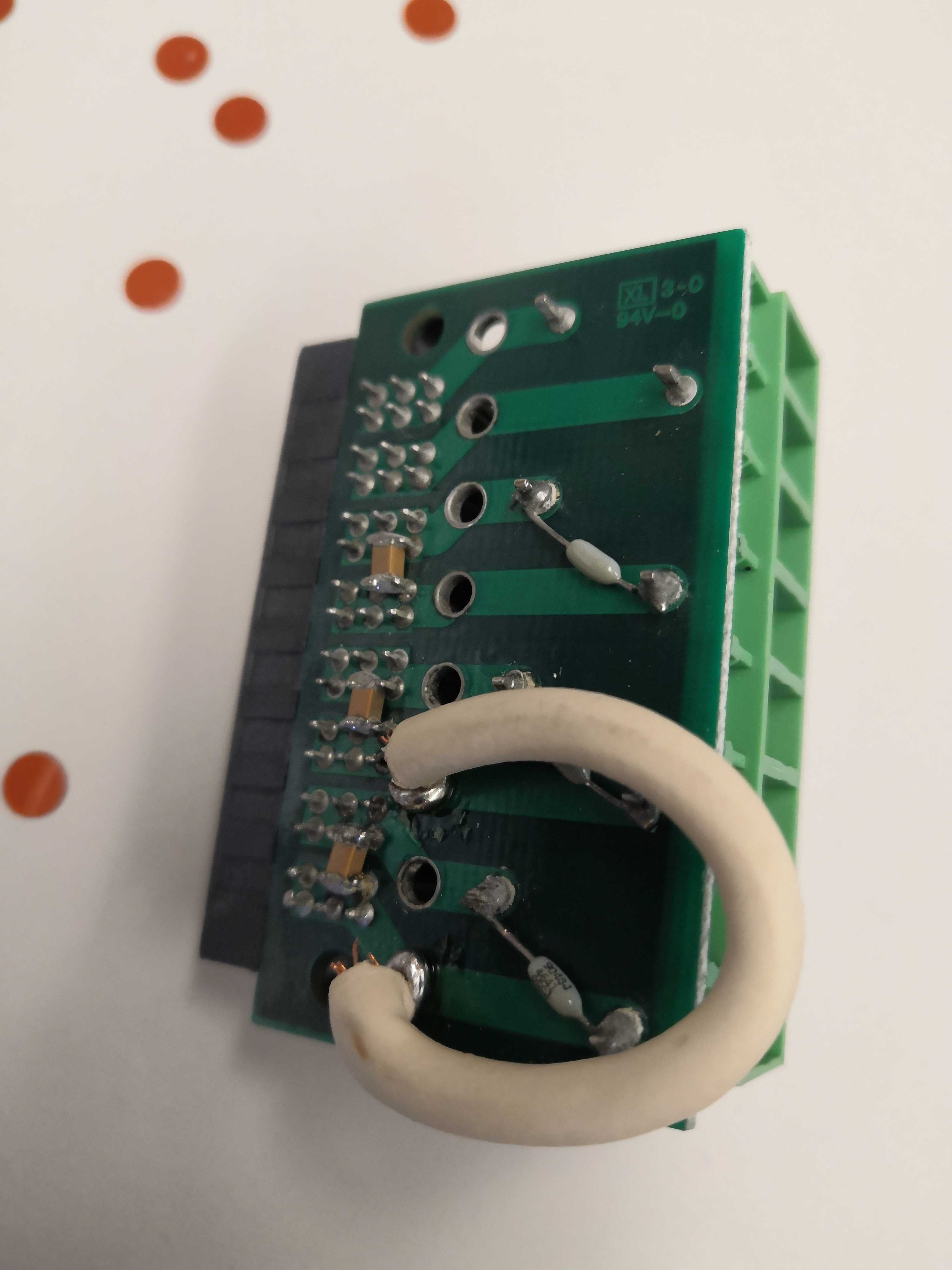
-
For
ACCMsOutput board for
ACCMs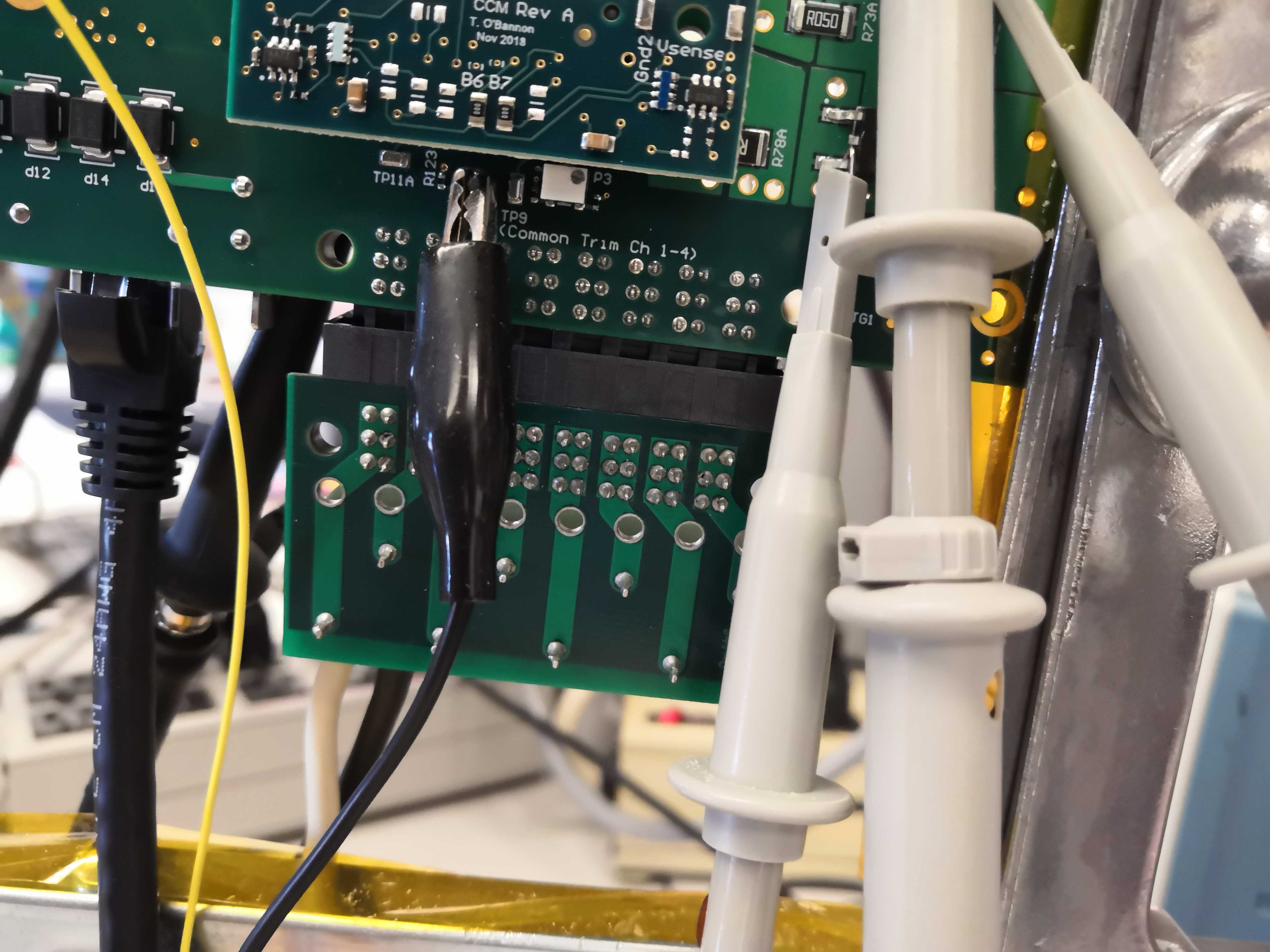
Stage 2: Capacitor Board
The second stage involves setting up the capacitor board. There are 2 different setting for the capacitor, each setting configuring the LVR for either 15MS/25A or 12A/12MS CCMs as indicated in the picture below. 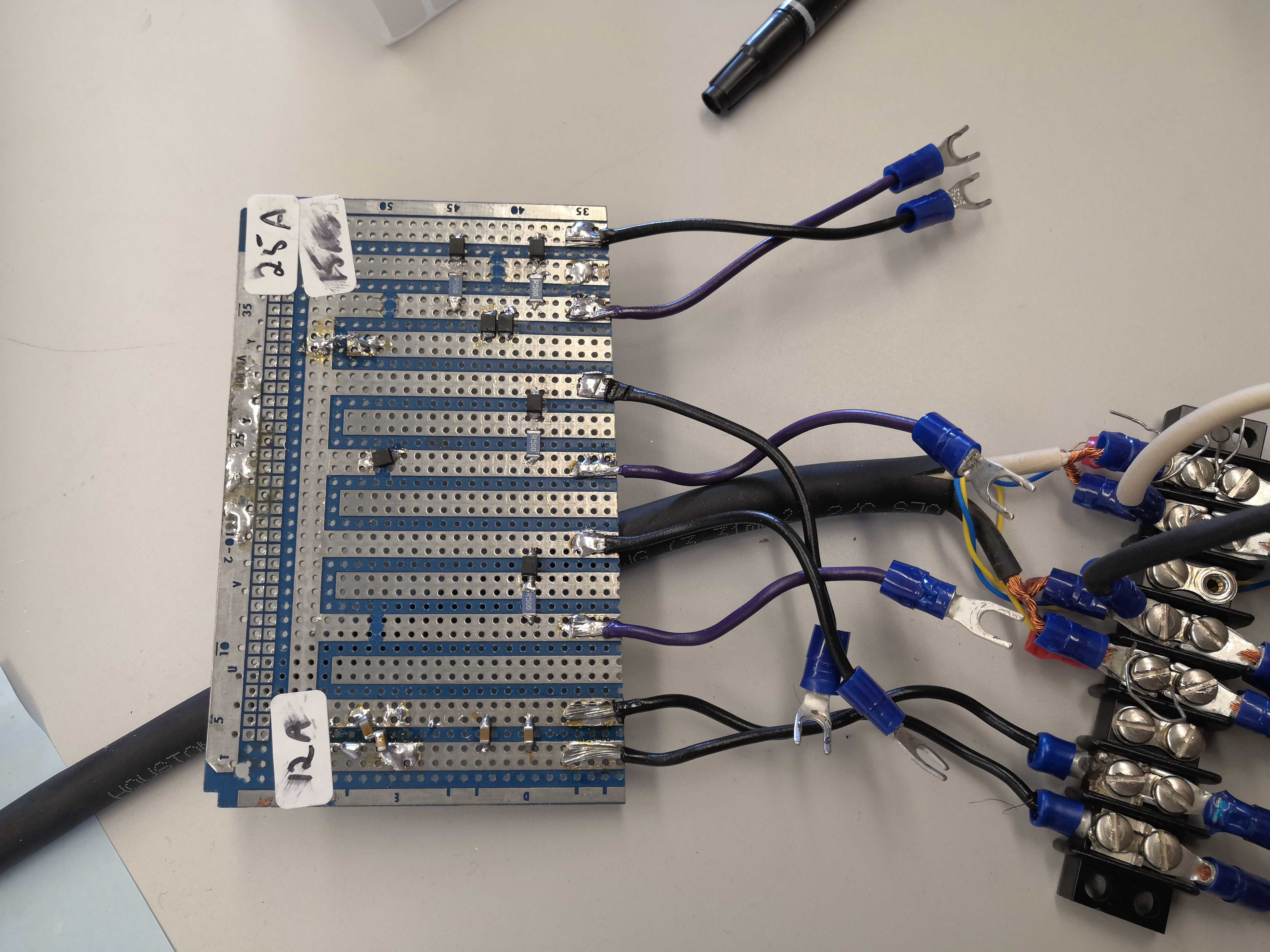
-
To configure
15MSand25ACCMs, connect the right most cables on the capacitor board to the left most sockets, as labeled by the 25A and 15MS tags shown in the figure above. Polarity matters, the purple cable is positive. -
To configure
12Aand12MSCCMs, connect the left most cables on the capacitor board to the left most sockets as connected in the picture shown above. Polarity does not matter.
Stage 3: Resistor Bank
The third and final stage involves configuring the resistor bank.
In this stage, you will be configuring the LVR to either 1.25, 1.5, or 2.5 V.
In general, when considering voltage and resistance, each channel that you use has 2.0-2.5 A running through it.
- For some CCM
XXA, the setup uses 2.0-2.5 A. - For some CCM
xxM + xxS, the setup would use 3.8-5.0 A.
When setting up the resistor bank, use jumpers to jump the resistor pins that you want. It does not matter how you jump the pins (since there are 3 per resistor) as long as the jumper goes over the middle pin. The jumper activates the resistor, which is added in parallel. Resistors are 0.5, 1, 2, and 5 Ohms.
-
To configure
15MSCCMs, connect the resistors with jumpers as shown below.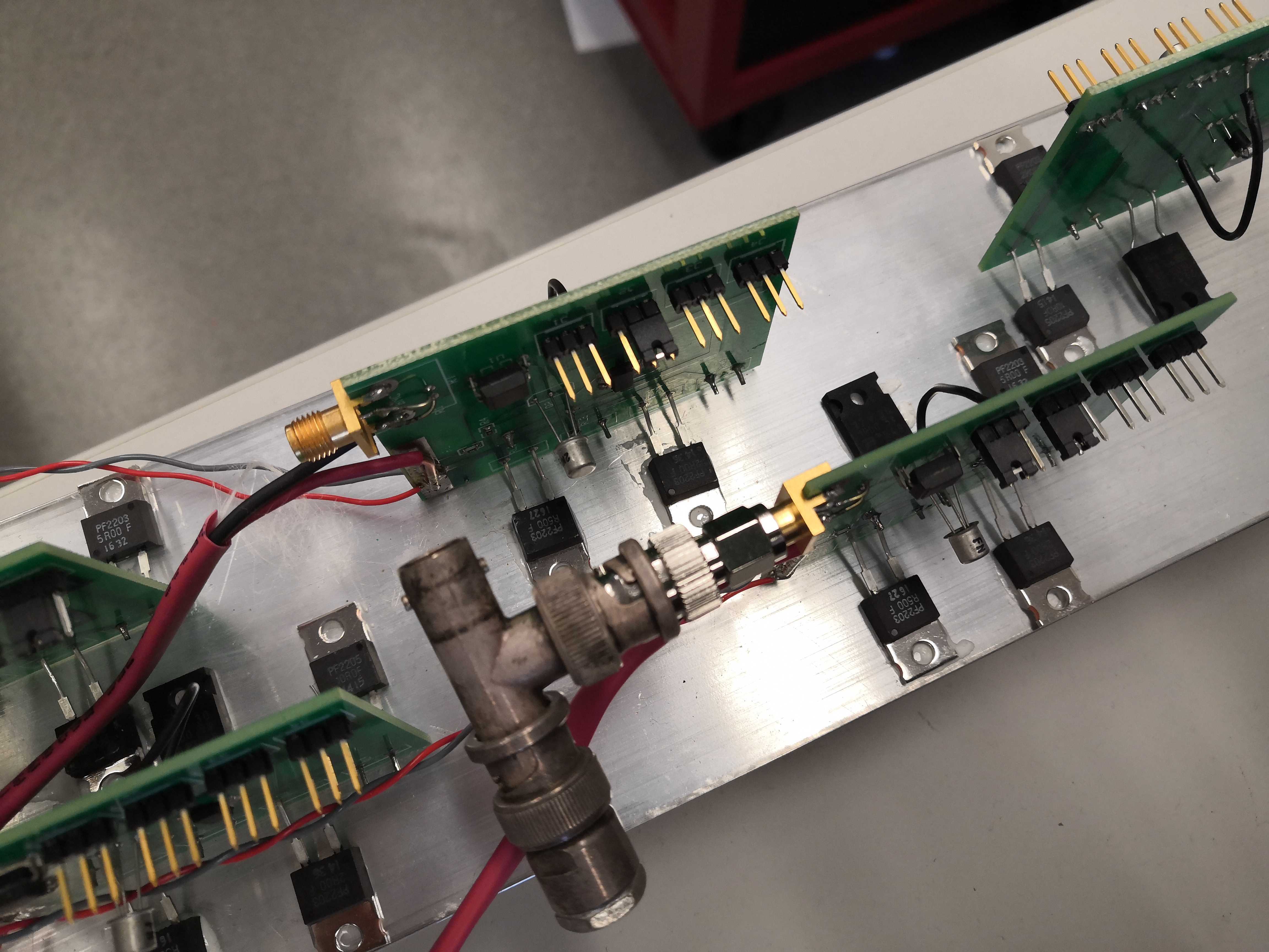
-
To configure
12ACCMs, connect the resistors with jumpers as shown below.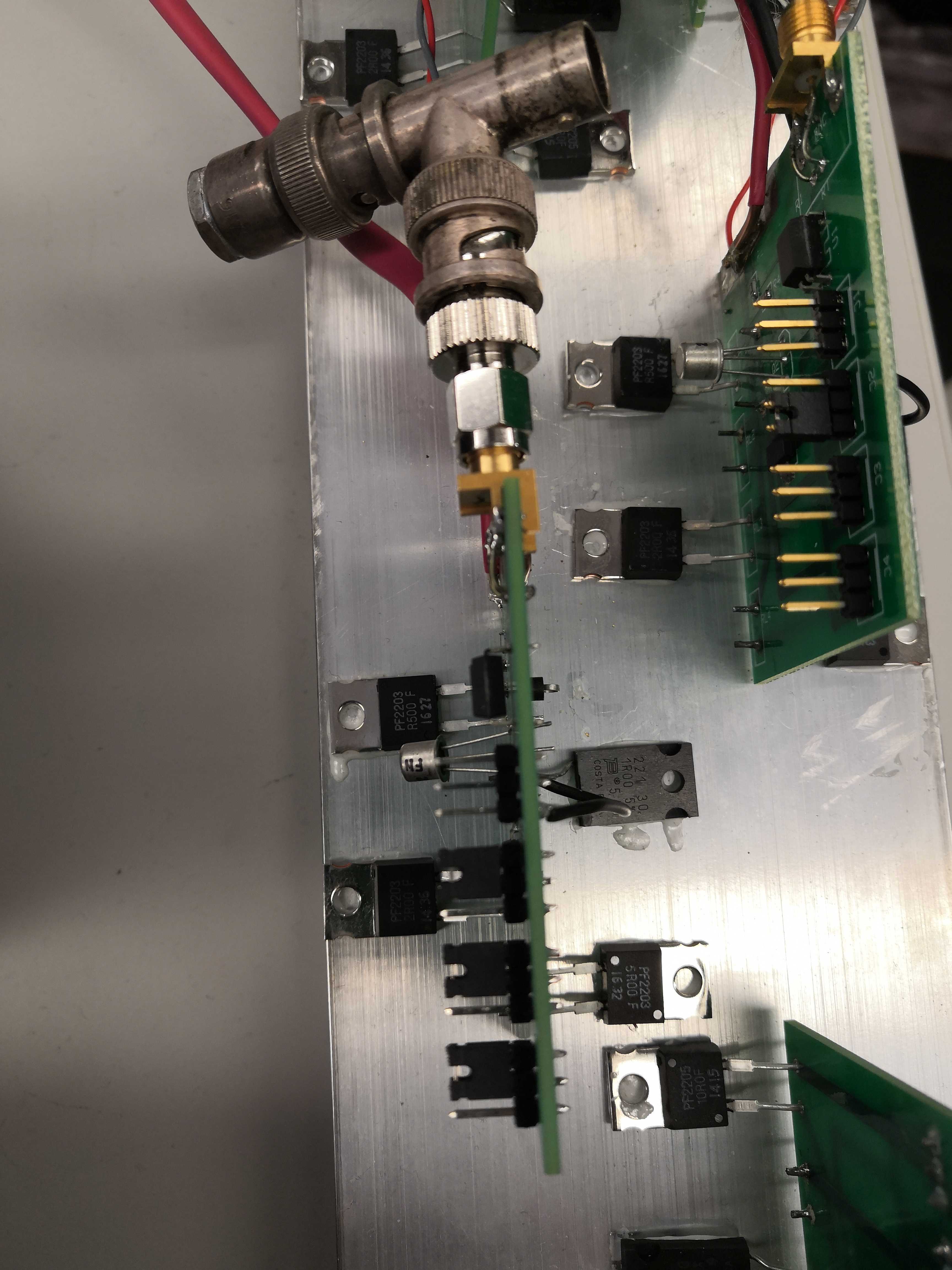
-
To configure
25ACCMs, connect the resistors with jumpers as shown below.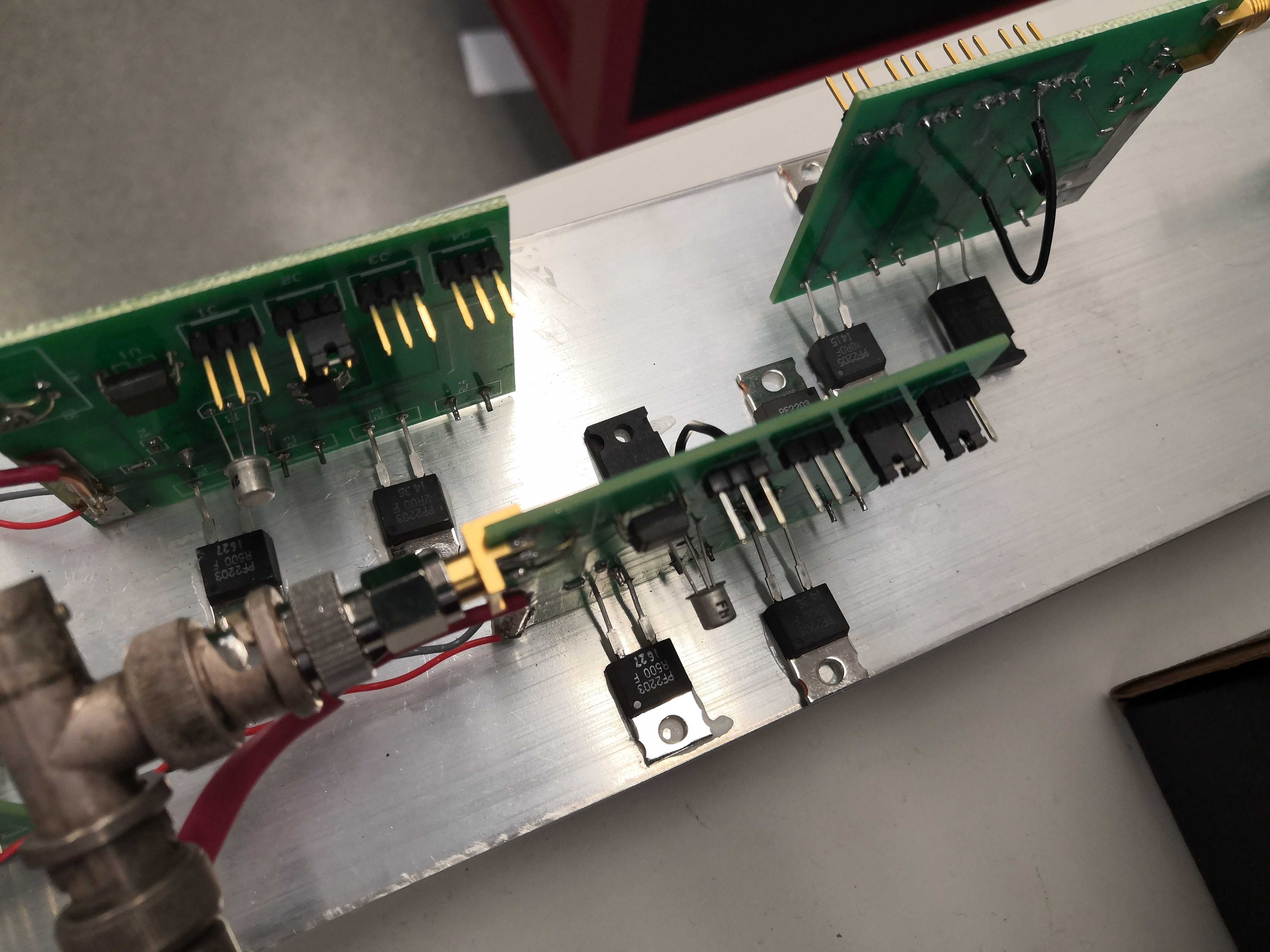
-
To configure
12MSCCMs, connect the resistors with jumpers as shown below.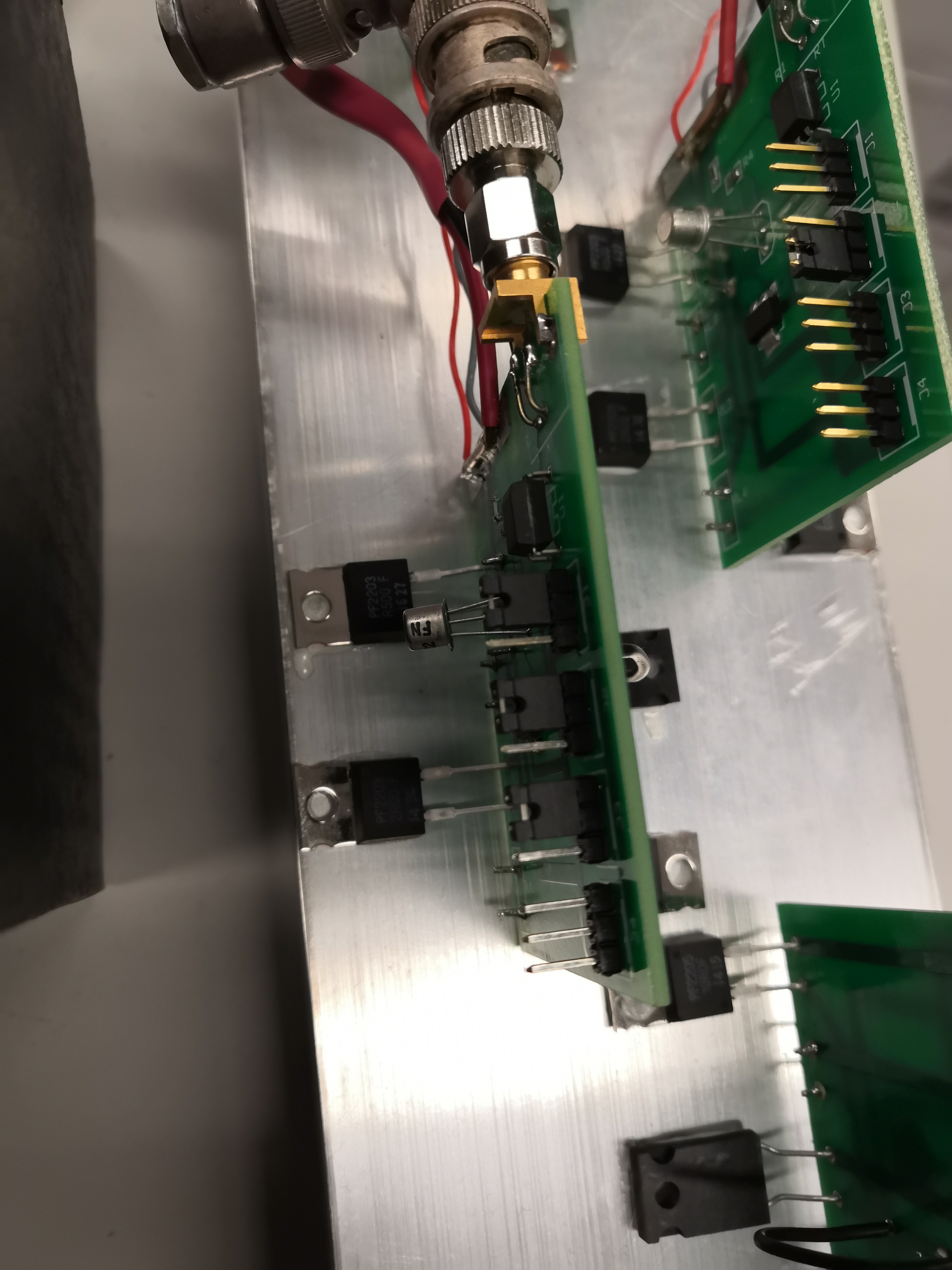
General CCM Test Stand Config:
Scope 1 should have channels 1 and 2 on. Channel 1 is connected to the load board, channel 2 is connected to pins 1 and 2 of the output connector.
Scope 2 should have channels 1 and 2 on for A, all channels on for MS. They are connected as shown
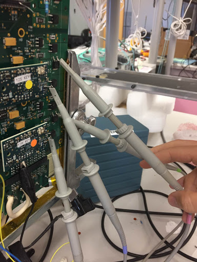
Channel 1/A is Master, 2/B is slave.
Unused channels should be disabled by switches or a resistor between pins 15 and 17.