Post-Burnin (final) QA Procedure
If you are already familiar with this procedure, you can simply follow the LVR final QA checklist.
Warning
You should not change the set up on the shelf with the oscilloscope and the loads. All you'll need to change during final QA are
- The connections to the LVR
- In the case of
MSboards, you'll need to add the jumper board to the MPSS black cables. It is easier to plug this board on the far end of the MPSS cable, and plug the other end of the MPSS cable directly to the LVR.
-
Put on the wrist strap, take a burned in LVR. Set the switches as indicated in the table below. Order refers to toggles 1234 on the switch, with
1meaningON. (CCM) or (FPGA) refer to the side of the LVR the switch is on. There are four SW6 switches, ABCD.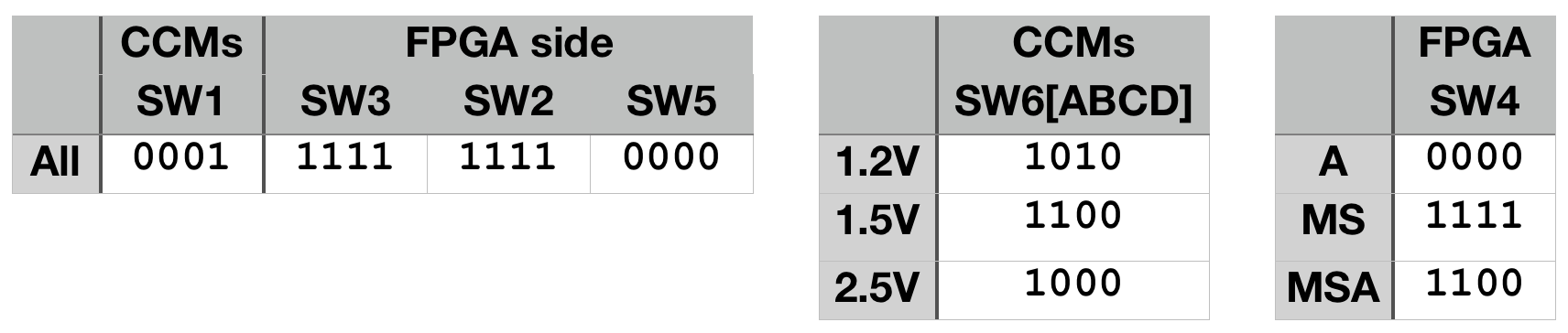
-
Confirm that the connection between
GND(eg,TP7) and EARTH (lugs sticking out at the bottom) is still > 25k Ohms in both directions. -
Slide LVR into the cooling frame, input side first. With the torque screwdriver set to 5.5 inch*pounds, tighten the wedge locks.
-
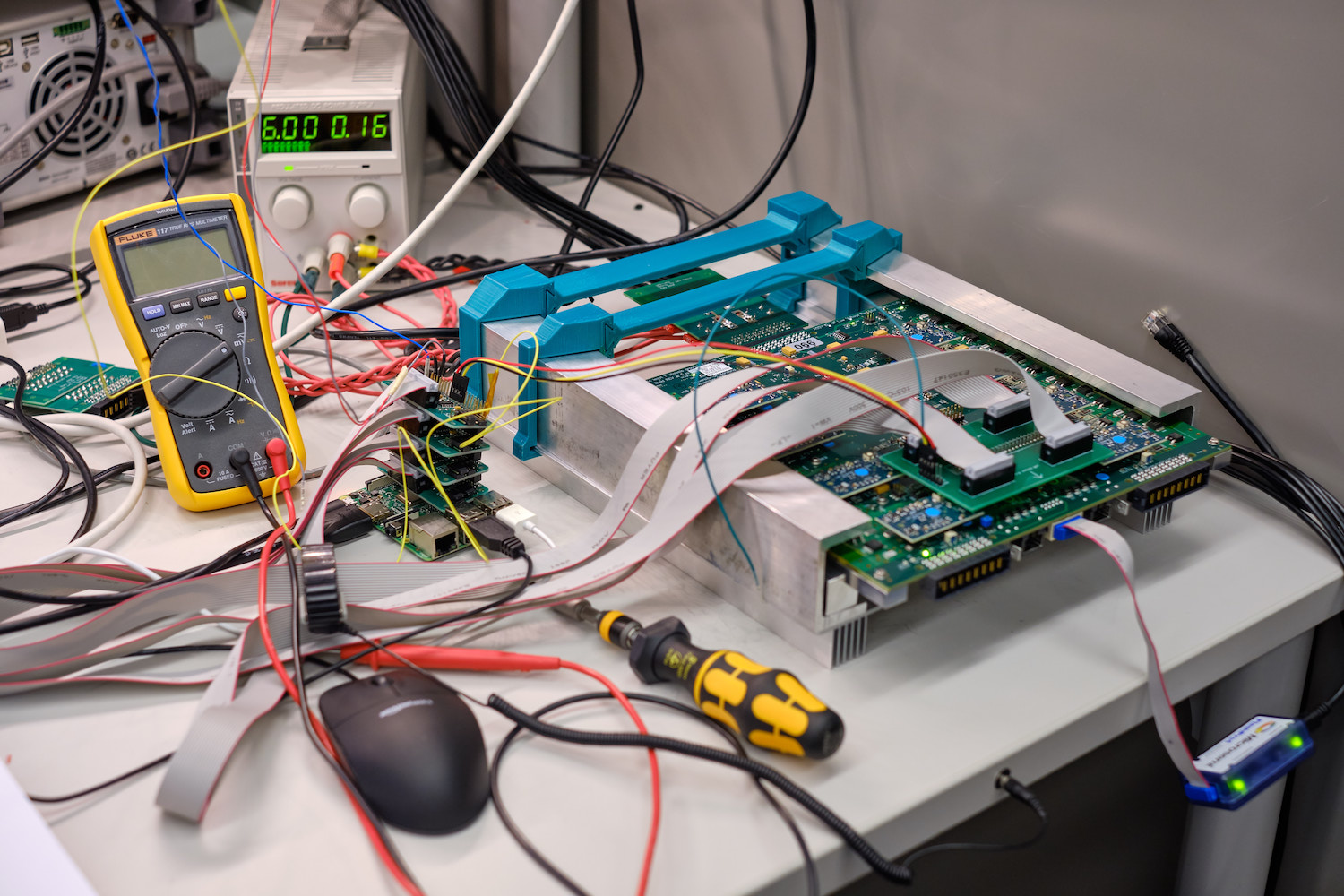
Connect input BB, the Rpi monitor, and turn on the PS at 6V as shown below.
- If fw version is not 2.06, also connect the Microsemi dongle, and update the firmware.
-
Adjust
P1,P2, andP5if the base voltages are not as expected (Vin_FPGA_1V5=1.5 V,Vin_FPGA_3V3=3.3 V,V_OPAMP_RAIL=5.5 V) -
Using the Rpi Butler software, request WORD2 to confirm fw version is 2.06, and turn all channel
ON -
Adjust the CCM potentiometers if the
V_SENSE_MONivoltages are not about 1.25V, 1.52V, or 2.51V. -
Reduce power supply voltage to about 4.3V (1.2V LVR), 4.8V (1.5V LVR), or 5.3V (2.5V LVR) and check the under-voltage lockout (UVL) turns all channels off in the Rpi monitor.
- Set input voltage back to 6V
-
Change SW1 to
0011, and check the over-temperature protection turns all channels off and theLD7LED turns on. Some times you may have to go all the way to1111. Afterwards change SW1 back to0001. -
Set all channels to
READYwith the Rpi Butler, and adjustP3andP4such that theV_SENSE_MONivoltages are between 110-190 mV (preferably 120-140 mV). -
Repeat these steps after setting all channels to
OFFwith the Rpi Butler and connecting the MPSS cable and RJ45 sense lines to each output. ForMSLVRs, you will need to connect the jumper board to the MPSS cable (easier on the end away from the LVR):- Set the oscilloscope trigger to Single, the Butler to "Ripple ALL", and check that the turn-on curve is smooth and comes to a sensible voltage (scope is single ended, so voltage will be higher than
V_SENSE_MONi). LVRs without slaves would look like on the left,MSlike on the right.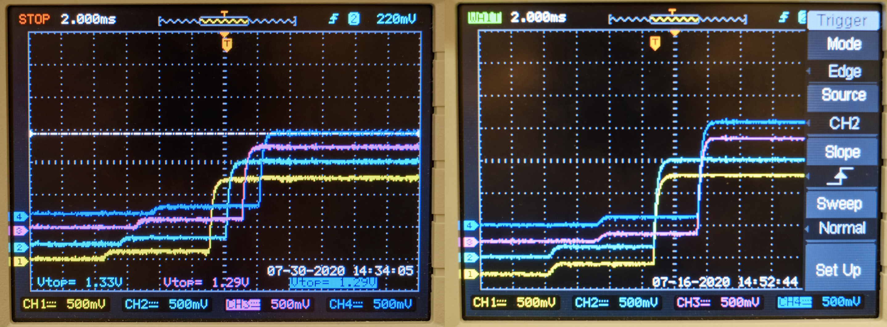
- Confirm with multimeter that the voltage drops across resistors
R73[A-H]andR91[A-H]for each channel match one-another to within 2-5%. These are the two medium-sized resistors with R050 and R150 printed on them. It is okay if the values do not match between different channels. - Check the sense lines by verifying that when the sense line cable is disconnected the
V_REG_OUTfor the connected channels moves until it matches the other half of the LVR.
- Set the oscilloscope trigger to Single, the Butler to "Ripple ALL", and check that the turn-on curve is smooth and comes to a sensible voltage (scope is single ended, so voltage will be higher than
-
The LVR can be shut down and set the JTAG into a radiation-hard state by moving the two jumpers on
J22(near ch8) to connect pins 4&6 and pins 3&5 (should be both jumpers moving one pin to the right if the output is facing you.) -
Set the LVR to its final configuration. Consult the database for valid 'sub types' and remove CCMS as necessary. For each removed CCM, one of the switches on SW3 and SW2 must be set off. Also, if removing an MS pair, turn off the corresponding switch on SW4. Use a marker to X off the stickers of removed CCMs.
SW3 toggle Channels SW2 toggle Channels SW4 toggle Channels (Slave) 1 CH1 1 CH5 1 CH2 2 CH2 2 CH6 2 CH4 3 CH3 3 CH7 3 CH6 4 CH4 4 CH8 4 CH8 -
Update the database, and you are done!